63
4
Design and Functions
4.7
Flue Gas Recirculation
To recirculate exhaust gases from the flue, either the combustion air fan or a recirculation fan
can be used. If a recirculation fan is used then it is controlled in parallel with the combustion
air fan.
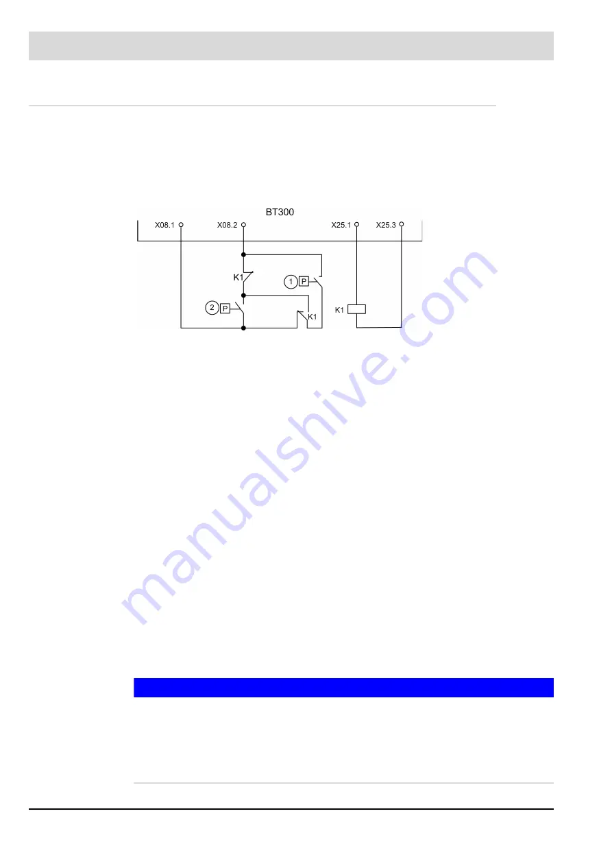
The operation of a recirculation fan is controlled by either a differential pressure switch mount-
ed across the fan or an absolute pressure switch mounted on the fan's positive pressure side.
Negative pressure created by the combustion air fan can be used as an alternative to a recir-
culation fan to aspirate flue gases. For this method of flue gas recirculation it is sufficient to
monitor the combustion air fan. It is not possible to use a VSD controlled recirculation fan with
the BT300 system.
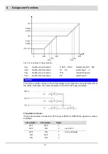
Program Sequence of BT300 with Flue Gas Recirculation
The action of the fuel and air actuators is not affected by the flue gas recirculation.
The recirculation damper stays closed at the beginning of the pre-purge period.
After the adjusted delay (P 414) the pre-purge period is stopped temporarily and the recircu-
lation channel runs to OPEN position.
After the end of the pre-purge period the air damper runs to the ignition position. The fuel ac-
tuators are already in ignition position and the recirculation channel runs to CLOSE position.
After reaching this position, the burner ignites.
Only the fuel and air actuators run to the curve after the BT300 has changed to CONTROL
mode.
The recirculation channel remains at its position until the release conditions were met.
Subsequently the recirculation channel runs to the curve.
The recirculation channel is only released once the time period set in P331 has expired and
the release temperature P332 has been met.
If the temperature drops below the threshold set in P332 during operation the recirculation re-
mains active.
The recirculation channel runs to the CLOSE position at a flue gas temperature of 0 °C (32 °F)
– interruption of the temperature sensor.
During decommissioning the program sequence remains the same for fuel and air actuators.
The recirculation channel will be closed together with the fuel actuator.
NOTICE
Up to BT300 V3.5 an LCM100 is always required.
BT300 V3.6 and higher can also activate the recirculation channel by a delay time without
LCM 100.
If P 332 = 0 and no LCM 100 is connected, flue gas recirculation is permanently activated.
Terminals 29 and 30 must always be short-circuited at the LCM100 regardless of whether a
temperature sensor is connected or not.
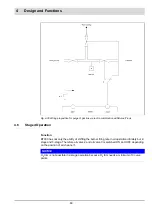
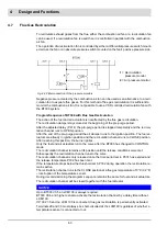
Fig. 4-32 Interconnection of the pressure monitors
1
= Recirculation
pressure monitor
2
= Air pressure monitor
Summary of Contents for BT300 BurnerTronic
Page 2: ......
Page 25: ...24 3 Product Description Fig 3 9 Temperature derating BT300 for operation 2000 m NHN...
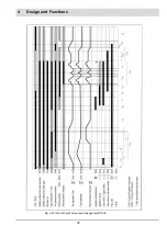
Page 49: ...48 4 Design and Functions Fig 4 20 Oil with pilot burner BT300...
Page 50: ...49 4 Design and Functions Fig 4 21 Oil without pilot burner BT300...
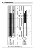
Page 51: ...50 4 Design and Functions Fig 4 22 Gas with pilot burner and leakage test BT300...
Page 52: ...51 4 Design and Functions Fig 4 23 Gas without pilot burner and leakage test BT300...
Page 53: ...52 4 Design and Functions Fig 4 24 Oil without pilot burner BT335...
Page 54: ...53 4 Design and Functions Fig 4 25 Gas without pilot burner and leakage test BT335...
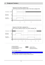
Page 59: ...58 4 Design and Functions Fig 4 28 Leakage test process diagram...
Page 98: ...97 6 Operating Control and Displays...
Page 99: ...98 6 Operating Control and Displays...
Page 103: ...102 6 Operating Control and Displays...
Page 105: ...104 6 Operating Control and Displays...
Page 106: ...105 6 Operating Control and Displays...
Page 107: ...106 6 Operating Control and Displays...
Page 109: ...108 6 Operating Control and Displays...
Page 126: ...125 6 Operating Control and Displays 6 3 4 2 Curve Table Fig 6 37 Curve table window...
Page 246: ...242 10 EU Declaration of Conformity 10 EU Declaration of Conformity...
Page 247: ...243 10 EU Declaration of Conformity...


