64
4
Design and Functions
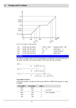
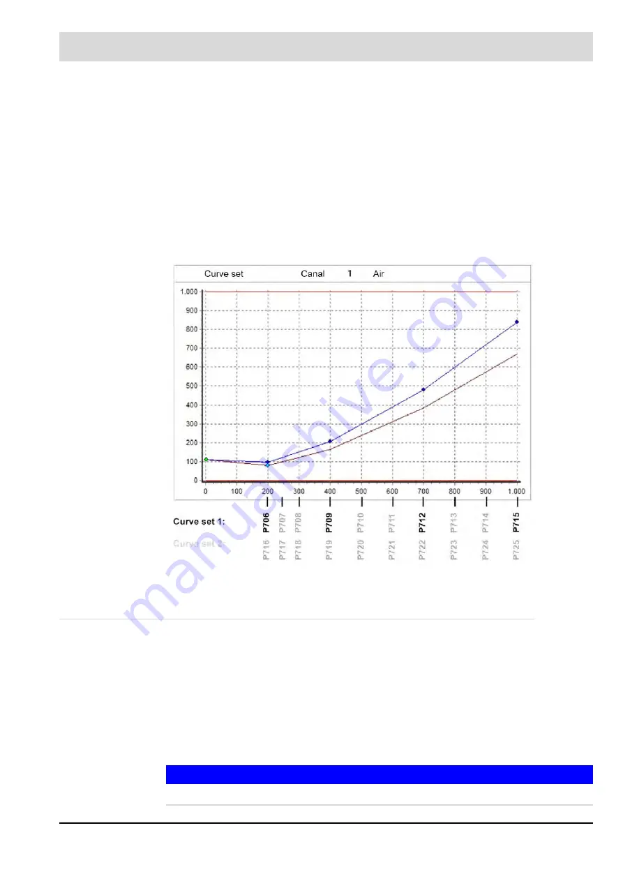
Correction of Ratio Curve "Air" for Inactive Flue Gas Recirculation
Reason for This Function
When a burner is operated with flue gas recirculation, it might be necessary for the combustion
air damper to be opened wider during operation with flue gas recirculation than in operation with-
out flue gas recirculation. If burner is activated without flue gas recirculation, this may cause con-
siderable air excess. Using the function "correction of ratio curve - air", the combustion air
damper position for inactive flue gas recirculation can be reduced (closed) by up to 20,0%.
Description of Function
The correction channel is determined by the parameters 704 (for curve set 1) and 705 (for curve
set 2). Using parameters 706-715, the reduction of the air damper position at every programmed
point of the curve of curve set 1 can be adjusted. Using parameters 716-725, the reduction of the
air damper position at every programmed point of the curve of cufve set 2 can be adjusted.
Fig. 4-33 Correction of the ratio curve air with inactive flue gas recirculation
4.8
Continuous Purge
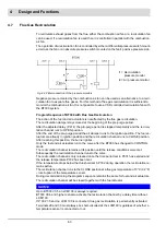
Requirement for continuous ventilation: P330 = 1
BT300 activates also the fan output in BURNER OFF mode and moves all control dampers
up to version 3.8.0.0 completely open.
From version 3.9.0.0, the pre-purge limits in parameters 365 - 369 are observed.
The "Burner ON" signal switches off the fan to check the air pressure switch.
As soon as the air pressure switch has switched off, the fan is switched on again and the burn-
er starts with the normal start-up sequence.
If the air pressure switch does not switch off after 25 s, BT300 changes to fault position and
indicates fault U929. Some internal faults of the BT300 also switch off the output for the fan.
NOTICE
The BT300 switches off the fan in the fault condition.
Summary of Contents for BT300 BurnerTronic
Page 2: ......
Page 25: ...24 3 Product Description Fig 3 9 Temperature derating BT300 for operation 2000 m NHN...
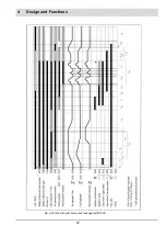
Page 49: ...48 4 Design and Functions Fig 4 20 Oil with pilot burner BT300...
Page 50: ...49 4 Design and Functions Fig 4 21 Oil without pilot burner BT300...
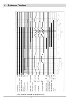
Page 51: ...50 4 Design and Functions Fig 4 22 Gas with pilot burner and leakage test BT300...
Page 52: ...51 4 Design and Functions Fig 4 23 Gas without pilot burner and leakage test BT300...
Page 53: ...52 4 Design and Functions Fig 4 24 Oil without pilot burner BT335...
Page 54: ...53 4 Design and Functions Fig 4 25 Gas without pilot burner and leakage test BT335...
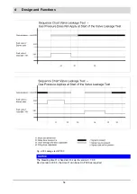
Page 59: ...58 4 Design and Functions Fig 4 28 Leakage test process diagram...
Page 98: ...97 6 Operating Control and Displays...
Page 99: ...98 6 Operating Control and Displays...
Page 103: ...102 6 Operating Control and Displays...
Page 105: ...104 6 Operating Control and Displays...
Page 106: ...105 6 Operating Control and Displays...
Page 107: ...106 6 Operating Control and Displays...
Page 109: ...108 6 Operating Control and Displays...
Page 126: ...125 6 Operating Control and Displays 6 3 4 2 Curve Table Fig 6 37 Curve table window...
Page 246: ...242 10 EU Declaration of Conformity 10 EU Declaration of Conformity...
Page 247: ...243 10 EU Declaration of Conformity...

