131
10
Appendix
Owing to the large number of usable transducers LAMTEC has only one two wire element and
one three wire element in it’s product range. It is selected in that way, that it covers a number
of measuring tasks. Other transducers only on enquiry or direct from the company Turck.
10.9.2 Selection of a Suitable R. P. M. Sensor
The correct sensor should always be selected, taking into account the structural features of
the element to be measured.
Since this element is not always known, the following is an approximation procedure for di-
mensioning the attenuating elements and selecting a suitable sensor.
In most cases, a shaft is sensed directly. One or several attenuating elements (screw-heads
or metal plates) are attached directly to the shaft. A symmetrical arrangement should be en-
sured, since many instruments work on the principle of measuring the period, and in the case
of more than one attenuating element require 100% equal intervals between them.
If this cannot be guaranteed, the signal can exhibit jumps (asymmetry can become particularly
noticeable in analogue signals). This problem can be solved by installing only one attenuating
element (this is the standard setting for rev. speed capture in the VMS).
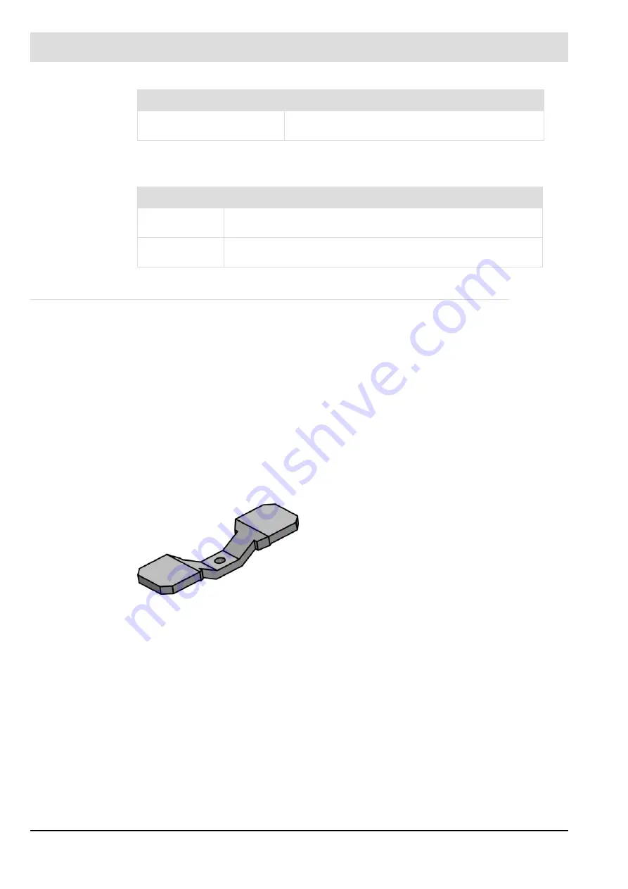
Example of an attenuating element:
Usable NAMUR transmit-
ters:
all Turck sensors, which contain Y0 or Y1 in their
type designation.
Item no.
Description
660R8101
r.p.m. sensor as a two wire system
d = 12 mm, switch gab 2 mm
663R8103
inductive sensor with switch terminals in three wire system
d = 12 mm, switch gab 4 mm
Technical Data
Fig. 10-12 Attenuating element (example)
Summary of Contents for VMS 4
Page 2: ......
Page 119: ...118 10 Appendix...
Page 129: ...128 10 Appendix Fig 10 9 Ger t 4 Ger t 5 with output regulator...
Page 141: ...140 10 Appendix 10 14 Declaration of Conformity...
Page 142: ...141 10 Appendix...
Page 143: ...142 10 Appendix 10 15 Protocol Example...
Page 144: ...143 10 Appendix 10 16 O2 Setpoint Curves...
Page 145: ...144 10 Appendix...


