39
Call 1-888-370-6531 for Technical Support
4.
Move or cover the heater and any other equipment that might be damaged by falling debris when the hole in the
roof is cut.
5.
Cut back the roof insulation to allow at least 2 inchs of clearance around the double-wall pipe. Due to the slope
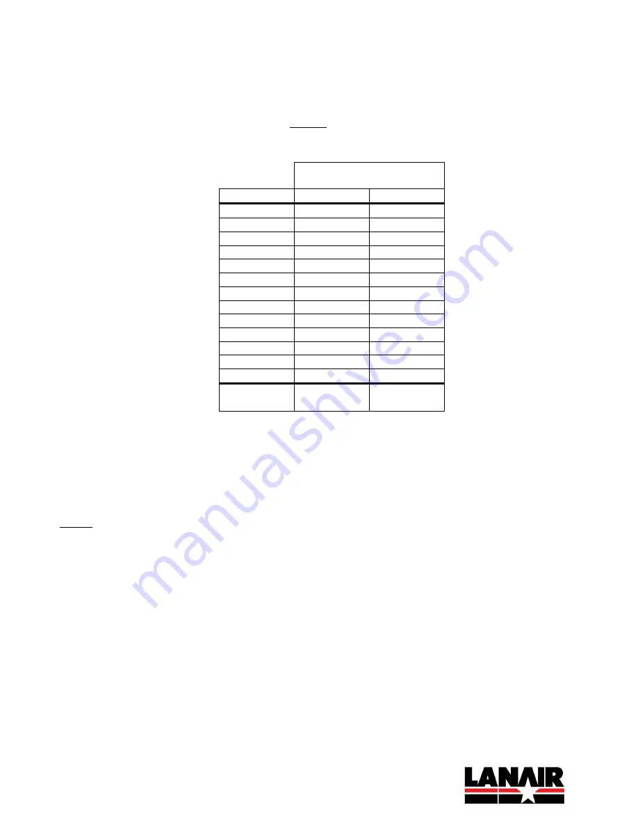
of the roof, the cut will be an oval, rather than just a circle. Use the 2” Clearance column in the table below to
determine the proper dimensions of the oval. NOTE: The roof slope is measured in inches of vertical rise per
foot of horizontal run (i.e., “0-12” is a flat roof and “12-12” is a roof with a 45 degree slope).
Width x Height of Oval
to Cut
Roof Slope
10 x
12 x
0-12
10.0
12.0
1-12
10.5
12.0
2-12
10.5
12.5
3-12
10.5
12.5
4-12
10.5
13.0
5-12
11.0
13.0
6-12
11.0
13.5
7-12
12.0
14.0
8-12
12.0
14.5
9-12
12.5
15.0
10-12
13.0
16.0
11-12
13.5
16.5
12-12
14.5
17.0
Applies
6" DW Flue
1" Clearance
6" DW Flue;
2" Clearance
OUTSIDE (ON ROOF)
6.
Locate pilot hole in roof and cut an oval hole around it (refer to chart above for hole sizing on sloped roof).
NOTE: For a metal roof, use the 1” Clearance column. For a combustible roof, use the 2” Clearance column.
7.
Loosely assemble Roof Mount Bracket per the instructions included with it. Slide the 3-foot long, double-wall
pipe through band on bracket, so band is 12 inches from male end of pipe, with “L” brackets towards female
end. Tighten band so pipe is locked in place. Leave nuts for the “L” brackets a little loose, so the angle can be
adjusted. [NOTE: The backet can also be flipped and mounted to structure underneath the roof from the
inside.]
8.
Insert the female end of the pipe through the hole in the roof and lower it down so the bracket rests on the roof.
9.
Align the bracket over the hole, with the “L” brackets running up/down the roof, and secure it to the roof with
the provided self-drilling screws, or with appropriate fasteners for the roof material.
10.
Install the 2-foot long, double-walled pipe onto the 3-foot long pipe. Twist to lock into place.
11.
Use a level to ensure the pipe is vertical and tighten the nuts on the “L” brackets to lock the angle.
Summary of Contents for MX 75
Page 2: ......
Page 41: ...8 Appendices 8 1 Wiring Diagram ...
Page 42: ......
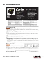
Page 43: ...34 Call 1 888 370 6531 for Technical Support 8 2 Primary Control Instructions ...
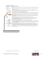
Page 44: ...35 Call 1 888 370 6531 for Technical Support Not used with RES 75 kBTU h units ...
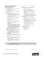
Page 45: ...36 Call 1 888 370 6531 for Technical Support No latch up with RES 75 kBTU h units ...
Page 46: ...37 Call 1 888 370 6531 for Technical Support ...
Page 54: ...45 Call 1 888 370 6531 for Technical Support 9 ...


