background image

PAGE 9

WS1TC & WS1.25 TC Manual 

Page 13

6

2

4b

4a

5

1

3

7

8

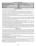
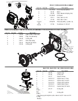
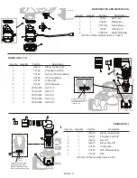
WS1TC Drive Cap Assembly, Down ow Piston, Regenerant Piston and Spacer Stack Assembly

Drawing No.

Order No.

Description

Quantity

1

V3005

WS1 Spacer Stack Assembly

1

2

V3004

Drive Cap ASY

1

3

V3178

WS1 Drive Back Plate

1

4

V3011

WS1 Piston Down ow ASY

1

5

V3174

WS1 Regenerant Piston

1

6

V3135

O-ring 228

1

7

V3180

O-ring 337

1

8

V3105

O-ring 215 (Distributer Tube)

1

Not Shown

V3001

WS1 Body ASY Down ow 

1

V3001-02

WS1 Mixing Valve Body ASY

Note: The regenerant piston is not used in backwash only applications.

Black Plug

4

Grey plug on all 

WS1.25 bodies

*Grey Ring

*Grey Distributor 

O-ring retainer

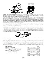
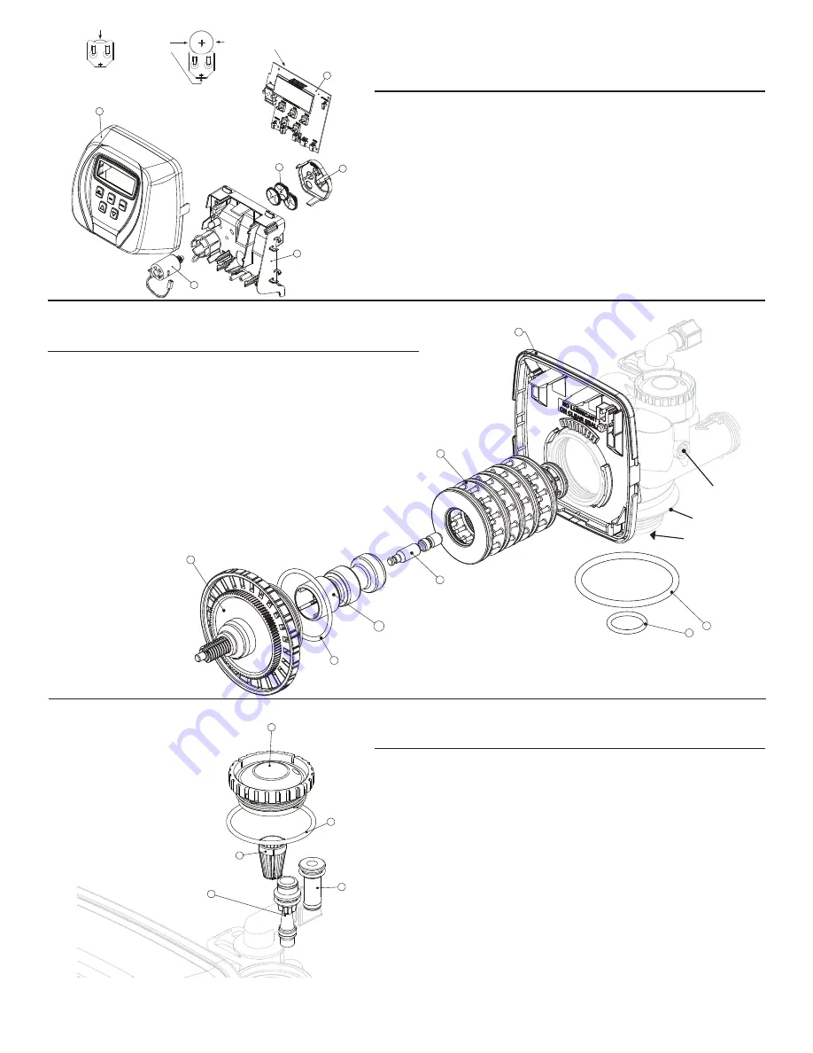
FRONT COVER AND DRIVE ASSEMBLY

Item No.

Quantity

Part No.

Description

1

1

V3175CC

Front Cover Assembly

2

1

V3107

Motor

3

1

V3106

Drive Bracket & Spring Clip

4

1

V3108CC

PC Board

5

3

V3110

Drive Gear 12 x 36

6

1

V3109

Drive Gear Cover

2 thru 6

V3002CC

Drive Assembly - (parts 2-6)

Not 

Shown

1

V3186

Transformer 110V-12V

DRIVE CAP ASSEMBLY, DOWNFLOW PISTON, REGENERANT PISTON AND SPACER  STACK ASSEMBLY

Item No.

Quantity

Part No.

Description

1

1

V3005

Spacer Stack  Assembly

2

1

V3004

Drive Cap Assembly

3

1

V3135

O-Ring 228

4

1

V3011

Piston Assembly

5

1

V3174

Regenerant Piston

6

1

V3180

O-Ring 337

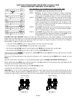
INJECTOR, INJECTOR CAP, SCREEN AND O-RING

Item No.

Quantity

Part No.

Description

1

1

V3176

Injector Cap

2

1

V3152

O-Ring 135

3

1

V3177

Injector Screen

4

1

V3010-1Z

Injector Assy  Z Plug

5

1

V3010-1C

Injector Assy C Violet

5

1

V3010-1E

Injector Assy E White

5

1

V3010-1F

Injector Assy F Blue

5

1

V3010-1G

Injector Assy G Yellow   

Not 

Shown

*

V3170

O-Ring 011

Not 

Shown

*

V3171

O-Ring 013

* Injector plug and injector each contain one 011 and one 013 

O-Ring

WS1 & WS1.25 Drawings & Service Manual 

Page 5

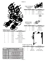
Injector Cap, Injector Screen, Injector, Plug and O-Ring

1

2

3

4

5

Drawing No.

Order No.

Description

Quantity

1

V3176

INJECTOR CAP

1

2

V3152

O-RING 135

1

3

V3177-01

INJECTOR SCREEN CAGE

1

4

V3010-1Z

WS1 INJECTOR ASY Z PLUG

1

5

V3010-1A

WS1 INJECTOR ASY A BLACK

1

V3010-1B

WS1 INJECTOR ASY B BROWN

V3010-1C

WS1 INJECTOR ASY C VIOLET

V3010-1D

WS1 INJECTOR ASY D RED

V3010-1E

WS1 INJECTOR ASY E WHITE

V3010-1F

WS1 INJECTOR ASY F BLUE

V3010-1G

WS1 INJECTOR ASY G YELLOW

V3010-1H

WS1 INJECTOR ASY H GREEN

V3010-1I

WS1 INJECTOR ASY I ORANGE

V3010-1J

WS1 INJECTOR ASY J LIGHT BLUE

V3010-1K

WS1 INJECTOR ASY K LIGHT 
GREEN

Not Shown

V3170

O-RING 011

*

Not Shown

V3171

O-RING 013

*

* The injector plug and the injector each contain one 011 (lower) and 013 (upper) o-ring.

Note: For up

 ow position, injector is located in the up hole and injector plug is in the 

other hole. WS1 up

 ow bodies are identi

 ed by having the DN marking removed.

Up

 ow option is not applicable to EE, EI, or TC control valves.

For a 

 lter that only backwashes, injector plugs are located in both holes.

CC Man u al


Page 3

1

2

3

5

6

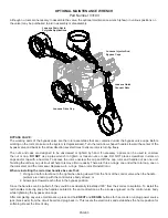
Battery replacement is 

3 volt lithium coin cell 

type 2032.

Correct 
Battery 

Orienta-

tion

Battery Fully Seated

When replacing the battery, align 

positives and push down to fully seat.

4

AC Adapter

U.S.

International

Supply Voltage

120 V AC

230V AC

Supply Frequency

60 Hz

50 Hz

Output Voltage

12 V AC

12 V AC

Output Current

500 mA

500 mA

CC Front Cover and Drive Assembly

Drawing No.

Order No.

Description

Quantity

1

V3175CC-01

WS1CC FRONT COVER ASSEMBLY

1

2

V3107-01

WS1 MOTOR

1

3

V3106-01

WS1 DRIVE BRACKET & SPRING CLIP

1

4

V3108CC-02BOARD*

WS1 THRU2L CC PCBRD ALT REPLACE

1

V3108CC-03BOARD*

WS1 THRU2L/2 CC PCB REPLACE

5

V3110

WS1 DRIVE REDUCING GEAR 12X36

3

6

V3109

WS1 DRIVE GEAR COVER

1

Not Shown

V3186

WS1 AC ADAPTER 110V-12V

1

V3186EU

WS1 AC ADAPTER 220-240V-12V EU

V3186UK

WS1 AC ADAPTER 220-240V-12V UK

V3186-01

WS1 AC ADAPTER CORD ONLY

Not Shown

V3178

WS1 DRIVE BACKPLATE

1

*Note: The V3108CC-02BOARD can be used on all valves except for WS2 valves.

Summary of Contents for 7-FESLES-24

Page 1: ...gned to give you many years of trouble free service When installed in accordance with the following instructions and if given reasonable care clear soft water will be the result For servicing and future inspection purposes please file this booklet with your important documents 7 LECS 50 7 FESLES 24 7 FESLES 32 7 FESLES 45 7 FESLES 60 7 LECS 75 7 LES 75 7 LES 100 7 LES 150 7 LES 200 ...

Page 2: ...t see Page 11 connect the fitting to the plumbing system first and then attach the nut split ring and o ring Heat from soldering or solvent cements may damage the nut split ring or o ring Solder joints should be cool and solvent cements should be set before installing the nut split ring and o ring Avoid getting primer and solvent cement on any part of the o rings split rings bypass valve or contro...

Page 3: ...r buttons AM PM toggles after 12 STEP 3 Press NEXT Set current minutes by pressing or buttons STEP 4 Press NEXT to exit SET CLOCK FIGURE 1 TO INSTALL 5 8 POLY TUBE DRAIN LINE The poly tube insert is shipped attached to the drain line elbow s locking clip Press the insert into the drain line 5 8 poly tube not included Loosen nut of the drain line elbow Press 5 8 poly tube with insert into the drain...

Page 4: ...sanitation methods FIGURE 3 FIGURE 2 PLACING UNIT INTO SERVICE Make sure inlet and outlet valves are to their closed positions If using optional bypass place in bypass position Turn on main water supply Open a cold water faucet This will clear the lines of any debris solder pipe dope etc that may be in the line Let water run at tap for a couple of minutes or until clear Turn off faucet Manually ad...

Page 5: ...a hammer To access the rotor unscrew the cap and lift the cap rotor and handle out as one unit Twisting the unit as you pull it out will help to remove it more easily There are three o rings one under the rotor cap one on the rotor stem and the rotor seal Replace worn o rings Clean rotor Reinstall rotor When reinstalling the red arrow handles be sure that 1 O rings on both rotors face to the right...

Page 6: ...pper right corner This helps the drive gears mesh with the drive cap assembly The drive bracket is properly seated when it snaps under the latches on the drive back plate If resistance is felt before latching then the notches are not fully engaged the piston rod is not in the hole the power wire is jammed between the drive bracket and the drive plate or the gear is not engaging the drive cap assem...

Page 7: ...atchet until the black o ring on the spacer stack assembly is no longer visible through the drain port Excessive force can break the notches molded into the drive back plate Make certain the main drive gear still turns freely The exact position of the piston is not important as long as the main drive gear turns freely Reattach the drive assembly to the control valve and connect all plugs After com...

Page 8: ...o the elbow until the o ring seats Remove locking clip push down on elbow to reseat and insert locking clip DO NOT use Vaseline oils or other unacceptable lubricants on o rings A silicone lubricant may be used on the o ring on the elbow or white retainer WATER METER OR METER PLUG The water meter assembly is connected to the PC board by a wire If the entire water meter assembly is to be replaced re...

Page 9: ...10 1Z Injector Assy Z Plug 5 1 V3010 1C Injector Assy C Violet 5 1 V3010 1E Injector Assy E White 5 1 V3010 1F Injector Assy F Blue 5 1 V3010 1G Injector Assy G Yellow Not Shown V3170 O Ring 011 Not Shown V3171 O Ring 013 Injector plug and injector each contain one 011 and one 013 O Ring WS1 25 Drawings Service Manual Page 5 Injector Cap Injector Screen Injector Plug and O Ring 1 2 3 4 5 Drawing N...

Page 10: ...lbow Male 1 5 V3163 O ring 019 1 6 V3159 01 WS1 DLFC Retainer ASY 1 7 V3162 007 WS1 DLFC 0 7 gpm for One DLFC must be used if tting is used V3162 010 WS1 DLFC 1 0 gpm for V3162 013 WS1 DLFC 1 3 gpm for V3162 017 WS1 DLFC 1 7 gpm for V3162 022 WS1 DLFC 2 2 gpm for V3162 027 WS1 DLFC 2 7 gpm for V3162 032 WS1 DLFC 3 2 gpm for V3162 042 WS1 DLFC 4 2 gpm for V3162 053 WS1 DLFC 5 3 gpm for V3162 065 WS...

Page 11: ...5 O Ring 215 4 2 V3149 1 PVC Male NPT Elbow Item No Quantity Part No Description 1 1 H4600 3 8 Safety Brine Valve 2 2 10151 Pin 3 1 H4640 32 Float Assembly 4 1 H4500 30 50 Air Check Assembly Item No Quantity Part No Description 1 2 V3151 Nut 1 Quick Connect 2 2 V3150 Split Ring 3 2 V3105 O Ring 215 4 2 V3145 Bypass 1 Rotor 5 2 V3146 Bypass Cap 6 2 V3147 Bypass Handle 7 2 V3148 Bypass Rotor Seal Re...

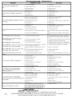
Page 12: ...h drive forces on piston c Replace piston s and spacer stack assembly d Control valve piston not in home position d Press NEXT and REGEN for 3 seconds or unplug power source jack black wire and plug back in to reset control valve e Motor not inserted fully to engage pinion motor wires broken or disconnected motor failure e Check motor and wiring Replace motor if necessary f Drive gear label dirty ...

Reviews: