PAGE 21
SPACER STACK ASSEMBLY:
To access the spacer stack assembly remove the drive assembly, drive cap assembly and piston. The spacer stack assembly can be
removed easily without tools by using thumb and forefinger. Inspect the black o-rings and clear lip seals for wear or damage. Replace
the entire stack if necessary. Do not disassemble the stack.
The spacer stack assembly may be chemically cleaned (dilute sodium bisulfite or vinegar) or wiped with a soft cloth.
The spacer stack assembly can be pushed in to the control valve body bore by hand. Since the spacer stack assembly can be
compressed it is easier to use a blunt object (5/8” to 1-1/8” in diameter) to push the center of the assembly into the control valve body.
The assembly is properly seated when at least four threads are exposed (approximately 5/8”). Do not force the spacer stack assembly
in. The control valve body bore interior can be lubricated with silicone to allow for easy insertion of the entire stack.
Reattach the drive cap assembly and piston(s) and the drive assembly.
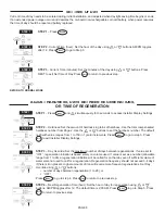
After completing any valve maintenance involving the drive assembly or the drive cap assembly and pistons unplug power source jack
from the printed circuit board (black wire) and plug back in or press and hold NEXT and REGEN buttons for 3 seconds.
This resets the electronics and establishes the service piston position. The display should flash all wording, then flash the software
version and then reset the valve to the service position.
INJECTOR CAP, SCREEN, INJECTOR PLUG AND INJECTOR:
Unscrew the injector cap and lift off. Loosen cap with special plastic wrench or pliers if necessary. Attached to the injector cap is a
screen. Remove the screen and clean if fouled.
The plug and/or injector can be pried out with a small screwdriver. The plug can be wiped clean. If the plug leaks replace the entire
plug. The injector consists of a throat and a nozzle. Chemically clean the injector with vinegar or sodium bisulfite. The holes can be
blown out with air. Both pieces have small diameter holes that control the flow rates of water to insure that the proper concentration
of regenerant is used. Sharp objects, which can score the plastic, should not be used to clean the injector. Scoring the injector or
increasing the diameter of the hole could change the operating parameters of the injector.
Push the plug(s) and/or injectors firmly in place, replace the screen and hand tighten the injector cap.
WATER METER:
The water meter assembly is connected to the PC board by a wire. If the entire water meter assembly is to be replaced, remove the
control valve cover and disconnect the power source and water meter plugs from the PC board. Unlatch the drive assembly and lean it
forward. Unthread the water meter wire from the side of the drive assembly and through the drive back plate. To reinstall, rethread the
water meter wire through the drive back plate and the side of the drive assembly. Reattach the drive assembly and the water meter and
power plugs.
THIS WATER METER SHOULD NOT BE USED AS THE PRIMARY MONITORING DEVICE FOR CRITICAL OR HEALTH EFFECT
APPLICATIONS.
OPERATING PRESSURES: 20 PSI MINIMUM / 125 PSI MAXIMUM • OPERATING TEMPERATURES: 40°F MINIMUM / 110°F
MAXIMUM
If no water meter wire is visible, then a plug is installed, not a water meter.
The water meter wire does not need to be removed from the PC board if the water meter is only being inspected and cleaned. To
remove the water meter assembly, unscrew the meter cap on the left side of the control valve. Pliers may be used to unscrew the nut if
necessary.
With the nut removed, a slot at the top of the water meter is visible. Twist a flat blade screwdriver in the slot between the control valve
body and the meter. When the meter is part way out it is easy to remove the water meter from the housing. Once the water meter is
removed from the control valve body, gently pull forward on the turbine to remove it from the shaft. Do not use a wire brush to clean the
turbine. Wipe with a clean cloth or chemically clean in dilute sodium bisulfite or vinegar. The turbine can be immersed in the chemical.
Do not immerse electronics. If the turbine is scored or damaged or the bearings on the turbine are worn, replace the turbine.
Do not lubricate the turbine shaft. The turbine shaft bearings are prelubricated. Do not use Vaseline, oils, or other unacceptable
lubricants on the o-ring. A silicone lubricant may be used on the black o-ring.
Snap the turbine on the shaft and reinsert the water meter into the side slot. Hand tighten the nut. Do not use a pipe wrench to tighten
nut.


