PAGE 6
WATER SOFTENER
PRESSURE
TANK
BYPASS PLUMBING
RECOMMENDED
IF
OPTIONAL BP2000
BYPASS VALVE
IS NOT USED.
BRINE TANK
FROM
WELL PUMP
MINIMUM 10 FEET
BETWEEN
WATER SOFTENER OUTLET
AND
WATER HEATER INLET
WATER SOFTENER
BYPASS PLUMBING
RECOMMENDED
IF
OPTIONAL BP2000
BYPASS VALVE
IS NOT USED.
TO
DRAIN
TO
OUTSIDE
TAP
BRINE TANK
WATER
HEATER
DRAIN LINE
AIR GAP
ADAPTER
FROM
WATER MAIN
COLD
HOT
MINIMUM 10 FEET
BETWEEN
WATER SOFTENER OUTLET
AND
WATER HEATER INLET
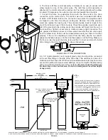
LOCATE WATER SOFTENER
AS CLOSE AS POSSIBLE
TO BRINE TANK.
A SIX FOOT LENGTH OF 3/8" O.D.
BRINE LINE POLYTUBE
SUPPLIED WITH BRINE TANK.
OVERFLOW GRAVITY DRAIN - ONLY USED IN CASE OF MALFUNCTION IN THE BRINE SHUTOFF. DO NOT CONNECT TO CONTROL VALVE DRAIN LINE.
IF UNIT IS INSTALLED WHERE OVERFLOW COULD CAUSE WATER DAMAGE, CONNECT TUBING AND RUN TO FLOOR DRAIN. DO NOT RUN TUBING ABOVE OVERFLOW HEIGHT.
WELL WATER
INSTALLATION
CITY WATER
INSTALLATION
WATER
METER
TO
DRAIN
TO
OUTSIDE
TAP
WATER
HEATER
DRAIN LINE
AIR GAP
ADAPTER
COLD
HOT
LOCATE WATER SOFTENER
AS CLOSE AS POSSIBLE
TO BRINE TANK.
A SIX FOOT LENGTH OF 3/8" O.D.
BRINE LINE POLYTUBE
SUPPLIED WITH BRINE TANK.
LOCATE WATER SOFTENER CLOSE TO A DRAIN.
AVOID OVERHEAD DRAIN LINES IF POSSIBLE TO
PREVENT BACK PRESSURE ON BRINE INJECTOR.
IF OVERHEAD DRAIN LINE IS USED AND EXCEEDS
5 FEET ABOVE CONNECTION ON CONTROL VALVE
OR
IF DRAIN LINE EXCEEDS 20 FEET IN LENGTH,
DRAIN LINE PIPE SIZE SHOULD BE MINIMUM 3/4".
OVERFLOW GRAVITY DRAIN - ONLY USED IN CASE OF MALFUNCTION IN THE BRINE SHUTOFF. DO NOT CONNECT TO CONTROL VALVE DRAIN LINE.
IF UNIT IS INSTALLED WHERE OVERFLOW COULD CAUSE WATER DAMAGE, CONNECT TUBING AND RUN TO FLOOR DRAIN. DO NOT RUN TUBING ABOVE OVERFLOW HEIGHT.
LOCATE WATER SOFTENER CLOSE TO A DRAIN.
AVOID OVERHEAD DRAIN LINES IF POSSIBLE TO
PREVENT BACK PRESSURE ON BRINE INJECTOR.
IF OVERHEAD DRAIN LINE IS USED AND EXCEEDS
5 FEET ABOVE CONNECTION ON CONTROL VALVE
OR
IF DRAIN LINE EXCEEDS 20 FEET IN LENGTH,
DRAIN LINE PIPE SIZE SHOULD BE MINIMUM 3/4".
Click to buy NOW!
PD
F-XCHANGE
w
ww
.docu-track.c
om
Click to buy NOW!
PD
F-XCHANGE
w
ww
.docu-track.c
om
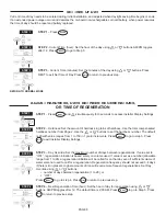
6. The brine refill flow control assembly is installed in an easy to access refill
elbow located on top of the control valve. The refill flow control assembly is
attached to the control valve with a locking clip. The locking clip allows the elbow
to rotate 270 degrees so the outlet can be oriented towards the brine tank.
7. Connect the brine line polytubing found with the brine tank to the brine
connection on the control valve. The control valve has a standard refill elbow
to which a 3/8” flexible tube can be connected, see
below. One polytube insert
is shipped on the brine line elbow’s locking clip. Remove this white polytube
insert and replace the locking clip. The second polytube insert is taped to the
top of the brine well cap in the brine tank. Press the polytube inserts into each
end of the provided brine tubing, press the polytube with insert into the nut on
the brine fitting. Tighten nut securely to create a pressure tight connection. The
nut, gripper and retainer sleeve is a three-piece assembly that can come apart
from the elbow body. Parts must be reassembled exactly as shown to function
properly. If the nut is completely removed from the body, slip the nut, plastic
gripper and retainer sleeve on to the tube then tighten on to the fitting. Make sure
the floor is clean beneath the brine tank and that it is level and smooth. Install
brine tubing to the brine tank using the above instructions.
BRINE LINE FITTING CONNECTIONS
DRAIN LINE FITTING CONNECTION USING 5/8" POLY TUBE
Click to buy NOW!
PD
F-XCHANGE
w
ww
.docu-track.c
om
Click to buy NOW!
PD
F-XCHANGE
w
ww
.docu-track.c
om
POLYTUBE
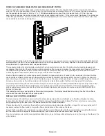
8. A 1/2” (inside diameter, not provided) gravity drain line should be connected
to the overflow fitting on the side of the brine tank. This overflow is in case of a
malfunction in the brine shut off. If the unit is installed where water may flow in the
event of an overflow and cause water damage, connect a length of flexible tubing
and run to a drain below the level of the overflow.
(Do not connect the tubing to
the drain line on the control valve. Do not run tubing above overflow height
at any point.)
A
G
A
F
B
D
C
E


