PAGE 29
5) Injector Cap, Screen, Injector Plug and Injector
Disassembly and Inspection:
LXCV15 Body and LXCV2/LXCV2QC
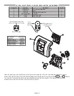
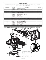
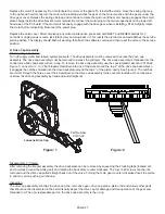
The injector can be accessed at the back of the valve by removing the threaded injector cap. The cap is removed by using
the V3193-02 service wrench (figure 1).
Once the cap is removed:
• LXCV15 valve can use the bottom threaded edge of the injector cap at an angle to pry out the injector
• LXCV2/LXCV2QC valves can use the open end of the V3193-02 service wrench at an angle to pry out the injector.
An injector consists of a throat and nozzle. It can be chemically cleaned with vinegar or dilute sodium bisulfate. The holes
can be blown out by air. Sharp objects, which can score the plastic, should not be used to clean the injector. Scoring the
injector or increasing the diameter of the injector hole could change the operating parameters of the injector.
If the LXCV15 valve does not use a regenerant the injector plug should not need to be cleaned, just verify that it has both
o-rings on the plug and that it is fully seated.
Reassembly:
Press injector into its bore hole and press until seated all the way down. Replace the injector cap.
6) Refill Flow Control Assembly or Refill Port Plug
Disassembly and Inspection:
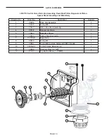
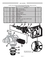
To clean or replace the refill flow control, remove the nut (2” valves) or pull out the locking clip (1.5” valves) and then pull
the fitting straight out. Remove the flow control retainer. The flow control can be removed by prying upward through the
side slots of the retainer with a small blade flat screwdriver, being careful not to mar the plastic seat.
Chemically clean the flow control or the flow control retainer using dilute sodium bisulfite or vinegar.
Do not clean with
abrasive methods.
If necessary, replace the flow control, o-ring on the flow control retainer, or the o-ring on the fitting.
Reassembly:
Insert the flow control into its seat, confirming correct flow control orientation. Reseat the flow control retainer and
reassemble the fitting (see diagram in the exploded view section).
Do not use Vaseline, oils, or other unacceptable lubricants on o-rings. A silicon lubricant may be used on the o-ring on the
elbow or the retainer, but not on the flow control or its seat.
Refill port plugs should not need to be service. O-rings may be replaced if necessary.
7) Regenerant Body
Disassembly and Inspection:
Turn off supply water & relieve system pressure.
The regenerant body would typically only be removed for servicing of the injector screen (not applicable to 2” valves).
Removing the injector cap can allow much of the contained water to drain before removing the body. Remove the (4)
¼-20 screws, the body can then be pulled straight back off the main body taking care to not lose the o-ring between the
regenerant & main body. The injector screen is installed inside the plastic body behind the injector feed tube. The injector
screen can be pushed out from the half round hole feature behind the injector cap.
Reassembly:
Insert the injector feed and draw tubes into the main body, bottoming them out in their bores. Install the injector screen in
the 1.5 regenerant body, the small hole in the end of the screen will nest around a feature in the plastic body allowing the
large end to be flush with a step in the tube bore. Confirm the placement of the o-ring on the flange of the plastic body
then press the regenerant body straight onto the main body, assuring the o-rings engages the bore in the main body.
Install & tighten the (4) ¼-20 screws. The lower injector o-ring engages the ID of the injector tube which may push the
injector out of position when reinstalling the regenerant body. Verify the injector is seated all the way down into its bore,
then reinstall the injector cap.
Summary of Contents for LX15 Series
Page 34: ...PAGE 34 NOTES ...
Page 35: ...PAGE 35 ...

