background image

16

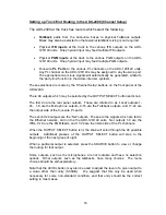
Setting up Truck End Routing in the ADX-2400 (Channel Setup)

The ADX-2400 at the truck has routers which select the following:

Talkback

  paths  from  the  announce  boxes  to  physical  Talkback  outputs.  

Mixes may also be selected so that external talkback mixing is not required.

Physical 

IFB  inputs

  at  the  truck  to  the  various  IFB  outputs  on  the  ADX-

120/140 units.  One physical input may feed multiple IFB outputs.

Physical 

PGM  inputs

  at the truck  to the various PGM outputs on the ADX-

120/140 units.  One physical input may feed multiple PGM outputs.

Four-wire 

PL  Ports

  to  the  various  PL  channels  on  the  ADX-120/140  units.  

Any PL channel on the ADX-120/140s may be assigned to any four-wire port. 
The appropriate mix-minus signals will automatically be generated, similar to 
the 'party-line' function in the Adam intercom systesm.

These selections are made by the 'Channel Setup' buttons on the front panel of the 
ADX-2400.

There 48 outputs which may be selected by the OUTPUT SELECT button and knob.

The first 24 are the rear panel outputs.  These are referred to as 'Local' outputs 1-
24.  1-8 are the Microphone outputs, 9-16 are the Talkback outputs, and 17-24 are 
the output side of the four-wire PL ports.

The second 24 outputs are the 'Net' outputs.  These are the signals which are fed to 
the  Ethernet  network,  and on the  the  ADX-120/140 units.    Net outputs  1-8  are  the 
IFBs, 9-16 are the PGM feeds, and 17-24 are the listen side of the PL channels.

When the OUTPUT SELECT button is lit, the knob will scroll through the 48 possible 
outputs.    Additional  presses  of  the  OUTPUT  SELECT  button  will  step  to  the 
beginning of the next group of eight.

When a particular output is selected, press the SOURCE button to view or change 
the routing for that output.

Some  outputs,  such  as  the  microphones,  are  not  routable  and  have  no  selection 
options.    Other  outputs,  such  as  the  talkbacks,  have  many  choices.    The  menu 
choices should be self-explanatory.

Note that the LEVEL button may also be used to adjust the level of a given output to 
a  value  other  than  unity  (0.00dB).      We  suggest  that  this  only  be  used  when 
necessary  for  some  non-standard  condition,  and  that  unity  should  be  the  correct 
setting in most cases.

Summary of Contents for ADX-140

Page 1: ...ORKED AUDIO INTERFACE UNIT Cobranet Version Installation and Operation Manual Firmware Version 5 5 Lance Design 27 Fairview Avenue Ridgefield Connecticut 06877 Tel 203 894 8206 Fax 203 894 8207 www lancedesign com ...

Page 2: ... subjected to mechanical or electrical abuse or modification as determined by Lance Design and also that the equipment is returned to Lance Design with prior authorization No liability whatsoever is assumed for consequential damages resulting from the use or failure of this equipment This warranty is in lieu of all other warranties expressed or implied including any implied warranty of fitness for...

Page 3: ...r is also available An LED indicator adjacent to each XLR indicates phantom power or line in mode Inputs 1 and 2 appear as Mics 1 and 2 at the truck Inputs 3 and 4 appear as talkbacks 1 and 2 since these inputs make use of the paths used for talkback signals in the ADX 120s This does NOT represent any compromise in quality they are full quality paths and intended to be used for mics or other on ai...

Page 4: ...he hybrids two wire to four wire conversion are carefully designed to provide good bandwidth and noise performance as well as a high level of trans hybrid loss In addition there are noise gates implemented in the dsp to provide additional quieting Because the long distance portions of the intercom are transmitted via a digital path and in four wire format the PL performance far exceeds what is typ...

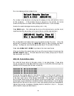
Page 5: ...nique system ID 01 99 The desired remote devices are designated in the ADX 2400 menu to be UNIT A UNIT B UNIT C and UNIT D for that ADX 2400 This is what determines the audio routing for example which microphone signal comes out of the Mic A1 output of the ADX 2400 The microphone signal that comes out of that output would be the headset mic Mic 1 from the ADX 120 which has its system ID switches s...

Page 6: ...Overload Condition 3 Sys System LED Green Normal No Faults Flashing Green Menu item changed Flash write pending Yellow Test Mode Internal Dipswitch Flashing Yellow Fault Condition Faults are either DC overload on any of the IFB or PL ports or that the ethernet port failover logic has selected the backup secondary port 4 Audio Link LED Off No audio packets being received Green Normal Audio packets ...

Page 7: ...gnments non interrupt program selection and IFB interrupt selection Each ADX 2400 can support up to four ADX 120s or ADX 140s thereby taking advantage of all 24 outgoing paths and all 24 incoming paths The ADX 120s and ADX 140s in use are distinguished from each other by the System ID numbers set on the switches on each unit and are assigned to be Unit A Unit B Unit C and Unit D in the ADX 2400 me...

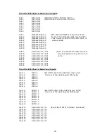
Page 8: ...ire PL Port 1 Out Each PL channel at the ADX 120 140s Out 18 4 Wire PL Port 2 Out may be assigned to any of the 4 wire Out 19 4 Wire PL Port 3 Out ports Out 20 4 Wire PL Port 4 Out Out 21 4 Wire PL Port 5 Out Out 22 4 Wire PL Port 6 Out Out 23 4 Wire PL Port 7 Out Out 24 4 Wire PL Port 8 Out The ADX 2400N Physical Rear Panel Inputs are Input 1 IFB In 1 Each IFB output at the ADX140s may be fed Inp...

Page 9: ...140 units One physical input may feed multiple IFB outputs Physical PGM inputs at the truck to the various PGM outputs on the ADX 120 140 units One physical input may feed multiple PGM outputs Four wire PL Ports to the various PL channels on the ADX 120 140 units Any PL channel on the ADX 120 140s may be assigned to any four wire port The appropriate mix minus signals will automatically be generat...

Page 10: ...el outputs and the outputs sent to the network and thus to the remote devices The DELAY function is not available in announce booth mode 3 The Remote Device menus Each remote device ADX 120 140 has an internal menu which may be accessed remotely via the ADX 2400 These menus configure the hardware of the remote device itself and are specific to the particular model i e the ADX 120 has different opt...

Page 11: ...o do this press the MENU button once and select config items 1 2 3 and 4 respectively using the knob When the desired item is selected press the MENU SET button and select the appropriate System ID number for the ADX120 or ADX140 you want to assign Pressing either SET or MENU will take you back to the item select mode Note If you re using a combination of ADX120 and ADX140 units it s best to assig...

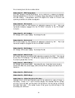
Page 12: ...es and you won t have to step backwards out of them ADX 140 Remote Menu Items The ADX 140 menu items for firmware version 1 0 are listed below These items may be accessed from the ADX 2400 front panel or via the RS 232 remote port on the ADX 140 front panel the Remote connector Config Item 01 Mic 1 Gain 25 70dB Config Item 02 Mic 2 Gain 25 70dB Config Item 03 Mic 3 Gain 25 70dB Config Item 04 Mic ...

Page 13: ...igured as 2 ch RTS format IFB1 on Ch1 PGM1 on Ch2 Dry IFB Configured as dry balanced 4 output of IFB 1 Dry PGM Configured as dry balanced 4 output of PGM 1 Dry Mic 1 Configured as dry balanced 4 output of Mic 1 Config Item 14 IFB 2 Mode Configures the IFB 2 output The selections are as follows Wet 2 Ch Configured as 2 ch RTS format IFB2 on Ch1 PGM2 on Ch2 Dry IFB Configured as dry balanced 4 outpu...

Page 14: ... connector Status Item 05 PL2 Voltage DC Voltage of PL2 power supply Nominally 25 volts Status Item 06 IFB1 Current DC Current drawn by the external IFB beltpacks powered by the IFB1 This should be less than 100 milliamps The IFB power supply will go into a shutdown condition if current is greater than 140 ma Status Item 07 IFB1 Voltage DC Voltage of IFB power supply Nominally 25 volts Note that i...

Page 15: ...ector The ADX 140 menus are also accessable via the RS 232 port in the Remote Control connector on the rear panel Although it s unlikely that you would need this function it allows configuration of the unit in a case where it might be operated with Cobranet hardware other than the ADX 2400 We also use it for test purposes in the shop The connector has a standard old fashioned PC modem pinout and w...

Page 16: ...nob The first 24 are the rear panel outputs These are referred to as Local outputs 1 24 1 8 are the Microphone outputs 9 16 are the Talkback outputs and 17 24 are the output side of the four wire PL ports The second 24 outputs are the Net outputs These are the signals which are fed to the Ethernet network and on the the ADX 120 140 units Net outputs 1 8 are the IFBs 9 16 are the PGM feeds and 17 2...

Page 17: ...t of the failure of one of the supplies The dual supplies also supply redundant power to the switch itself Insure a reliable AC power source in the remote location for the ADX units and for the Ethernet switch If there is any question about the reliability of the AC supply you might consider using a small UPS power supply to provide battery backup A small 500 watt unit intended for personal comput...

Page 18: ...m IFB 2 Output 2 channel wet RTS format or single channel dry 4dB nom PL Interface at ADX 140 2 channel wet RTS format DC current to support 3 beltpacks PL Interface Truck End 4 wire dry 4dBm nominal 8 assignable 4W Ports PL Trans hybrid Loss Greater than 55 dB at 440Hz Remote Control From ADX 2400 front panel or via RS232 Remote connector Front Panel Switches System ID two digit rotary switches S...

Page 19: ...ire PL Port 3 Out ports Out 20 4 Wire PL Port 4 Out Out 21 4 Wire PL Port 5 Out Out 22 4 Wire PL Port 6 Out Out 23 4 Wire PL Port 7 Out Out 24 4 Wire PL Port 8 Out The ADX 2400 Physical Rear Panel Inputs Input 1 IFB In 1 Each IFB output at the ADX140s may be fed Input 2 IFB In 2 from any of the eight physical IFB inputs Input 3 IFB In 3 Input 4 IFB In 4 Input 5 IFB In 5 Input 6 IFB In 6 Input 7 IF...

Page 20: ...CH 11 9 CH 19 9 CH 3 SHLD 22 CH 11 SHLD 22 CH 19 SHLD 22 CH 4 7 CH 12 7 CH 20 7 CH 4 20 CH 12 20 CH 20 20 CH 4 SHLD 8 CH 12 SHLD 8 CH 20 SHLD 8 CH 5 18 CH 13 18 CH 21 18 CH 5 6 CH 13 6 CH 21 6 CH 5 SHLD 19 CH 13 SHLD 19 CH 21 SHLD 19 CH 6 4 CH 14 4 CH 22 4 CH 6 17 CH 14 17 CH 22 17 CH 6 SHLD 5 CH 14 SHLD 5 CH 22 SHLD 5 CH 7 15 CH 15 15 CH 23 15 CH 7 3 CH 15 3 CH 23 3 CH 7 SHLD 16 CH 15 SHLD 16 CH ...

Page 21: ...Remote port is 38 4K Baud One Stop Bit No Parity GPIs 1 and 2 may be used to implement a talkback function for the first two mic inputs They may be controlled with a hand held pushbutton switch for example If GPI 1 is closed to ground switch between pins 5 and 6 on the connector Mic 1 is muted on its normal path and routed to the mic 3 TB1 path A rapidly flashing yellow LED adjacent to the Mic 3 c...

Page 22: ...22 NOTES ...
Reviews: