17
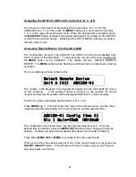
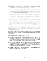
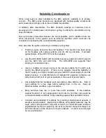
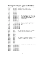
PGM A1 = Physical Input 9 [PGM In 1]
PGM A2 = Physical Input 10 [PGM In 2]
PGM B1 = Physical Input 11 [PGM In 3]
PGM B2 = Physical Input 12 [PGM In 4]
PGM C1 = Physical Input 13 [PGM In 5]
PGM C2 = Physical Input 14 [PGM In 6]
PGM D1 = Physical Input 15 [PGM In 7]
PGM D2 = Physical Input 16 [PGM In 8]
PL A1 = 4-Wire Port 1 [Physical Input/Output 17]
PL A2 = 4-Wire Port 2 [Physical Input/Output 18]
PL B1 = 4-Wire Port 3 [Physical Input/Output 19]
PL B2 = 4-Wire Port 4 [Physical Input/Output 20]
PL C1 = 4-Wire Port 5 [Physical Input/Output 21]
PL C2 = 4-Wire Port 6 [Physical Input/Output 22]
PL D1 = 4-Wire Port 7 [Physical Input/Output 23]
PL D2 = 4-Wire Port 8 [Physical Input/Output 24]
All Levels set to Unity [0.00 dB]
Please see the detailed Configuration section of this manual for more information.
The following items are STATUS items, and are only to display status
information. They may not be directly changed by the user.
Status Item 01 – Unit A RX Status (Active or Idle)
Displays ACTIVE status if data is being received by network receiver 1. This
receiver is used for audio signals coming from the remote device assigned as Unit
A.
Status Item 02 – Unit B RX Status (Active or Idle)
Same for receiver 2, audio signals coming from the Unit B remote device.
Status Item 03 – Unit C RX Status (Active or Idle)
Same for receiver 3, audio signals coming from the Unit C remote device.
Status Item 04 – Unit D RX Status (Active or Idle)
Same for receiver 4, audio signals coming from the Unit D remote device.
Status Item 05 – Output Reference (Int or Ext)
Indicates the timing reference for the AES outputs. If a valid reference signal (AES
silence or other AES signal) is applied to the rear panel 'AES Ref In' connector, the
unit will automatically switch to the Ext mode, and AES outputs will be syncronous
with the applied reference signal.

