13
32
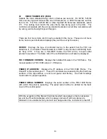
VIDEO FRAME RATE (25/30)
Selects the video standard being used, in frames per second. For NTSC, 525/60
SDI, and any high-def formats that use 30 frames/sec, or 29.97 frames/sec set this
item to ‘30’. For PAL, 625/25 SDI or other high-def 25 frame/sec standards, select
‘25’. This setting must match the video frame rate being used in the ddrs. The
controller will operate with the wrong standard selected, but all time calculations will
be wrong, and confusing things will happen.
There are four more items which may be selected in the menu. These are not menu
items, but are just information displays (they can’t be set by the users).
DEVICE:
Displays the type of controlled device, to the extent that the TDC can
determine it. If a Profile or Fast Forward is in ‘BVW’ mode, this item will identify them
as ‘Sony VTR’. If they are in Non-BVW modes, the TDC will try to report what
protocol is selected. The frame rate of the controlled device will also be displayed.
TDC FIRMWARE VERSION:
Displays the installed firmware in the TDC frame. This
manual applies to TDC-100B version 1.0 firmware.
FRAME IP ADDRESS:
Displays the IP address of the TDC-100B Frame. The
Panel IP is this number plus 1. These IP combinations are selected by the first three
sections of the dip switches on each unit (panel and frame). The switch settings
must match for proper operation.
FRAME SERIAL NUMBER:
Displays the serial number of the TDC-100B Frame
with which this panel is operating. The panel serial number is printed on the back
cover of the control panel.
With the exception of the Status Check items which are always turned on at power-
up, and the Pbus Data Display, which is always turned off, all menu items are
retained in non-volatile memory and will not change when the controller is turned off.
Summary of Contents for TDC-100B
Page 28: ...28 Notes...


