3
E. For the
soda water supply line
, the inlet water static pressure going into the carbonator pump
should NOT exceed 50 PSI
. If the static water pressure exceeds 50 psi, a water regulator must
be installed before the carbonator water inlet.
NOTE:
The Lancer Pressure Regulator, PN
The regulator must be installed as close as possible to the water carbonator pump inlet.
There is no minimum water pressure value feeding the carbonator. If the water pressure does
not exceed 50 psi, but fluctuates over this value (for example, when water usage on other
equipment connected to the same water supply causes pressure “spikes”), the use of a water
regulator is also required.
F.
Place CO
2
Cylinder with regulator in a serviceable location and route CO
2
supply line (75 PSI)
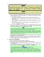
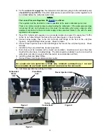
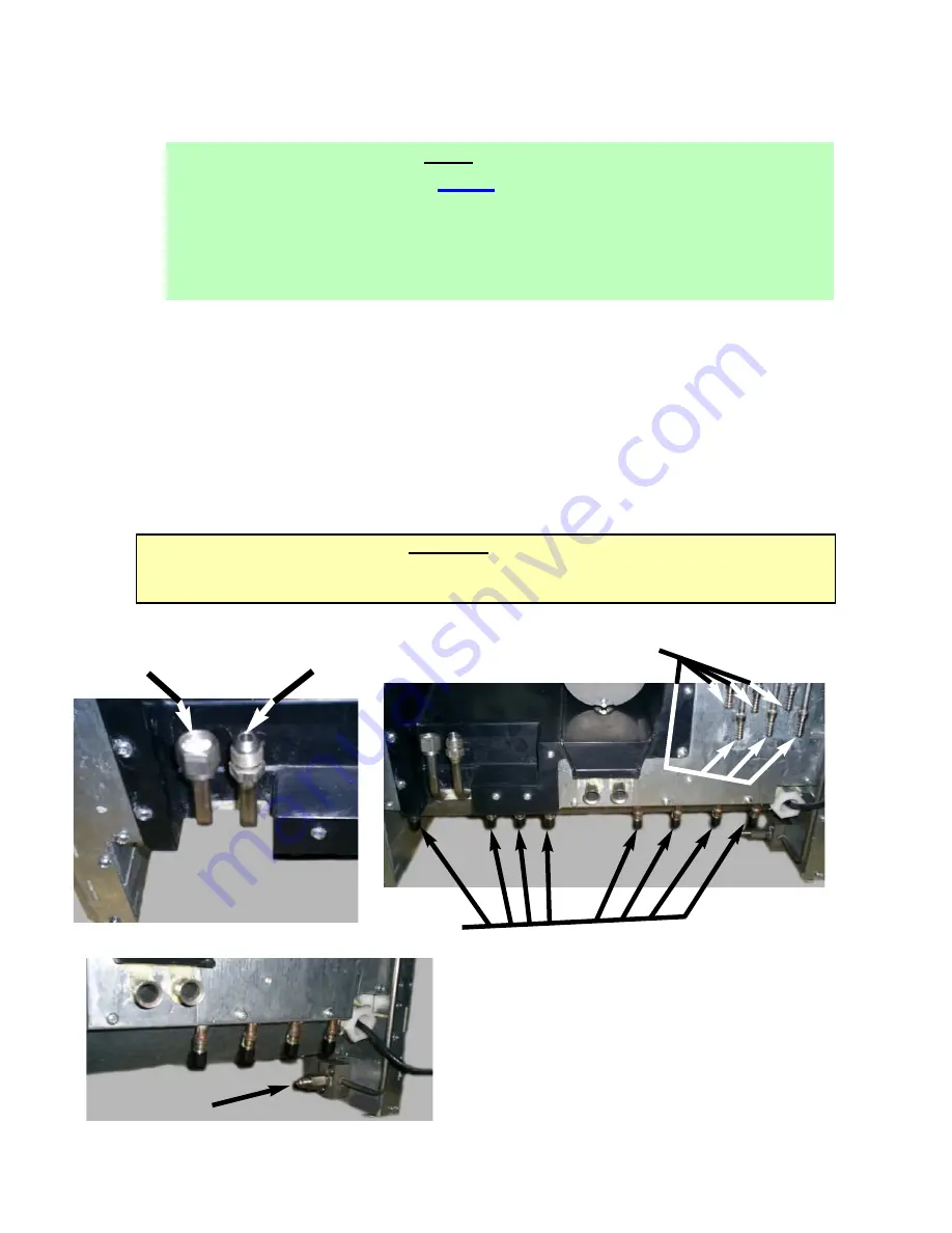
to the 1/4 inch flare fitting at the front of the unit (See Figure 3). Check for leaks.
G. Connect syrup supply lines to the 3/8 inch barb inlet fittings at the front of the unit (See
Figure 4), using BIB (Bag-In-Box) pumps. Check for leaks.
H. Connect flavor injection lines to the barb fittings at the front of the unit (See Figure 4). Check
for leaks.
I.
Install Drip Tray and extend hose to open type drain.
J.
Drain lines must be insulated with a closed cell insulation. Insulation must cover the entire
length of the drain hose, including fittings. The drain should be installed in such a manner that
water does not collect in sags or other low points, as condensation will form.
K. Install Cup Rest and Splash Plate.
L.
Connect Power Cord to grounded electrical outlet.
WARNING:
ICE AUGER AND BIN AGITATION SYSTEM WILL OPERATE AUTOMATICALLY. DO NOT
PLACE HANDS OR ANY BODY PARTS WITHIN THE BIN OR IN THE ICE CHUTE.
M. Test Motor operation by pushing Ice Chute.
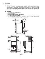
Figure 2
Plain Water
Inlet
Figure 4
Syrup
Connections
Flavor Injection Inlets
Figure 3
CO
2
Inlet
Carbonated
Water
Inlet


