background image

19

28-0752/02

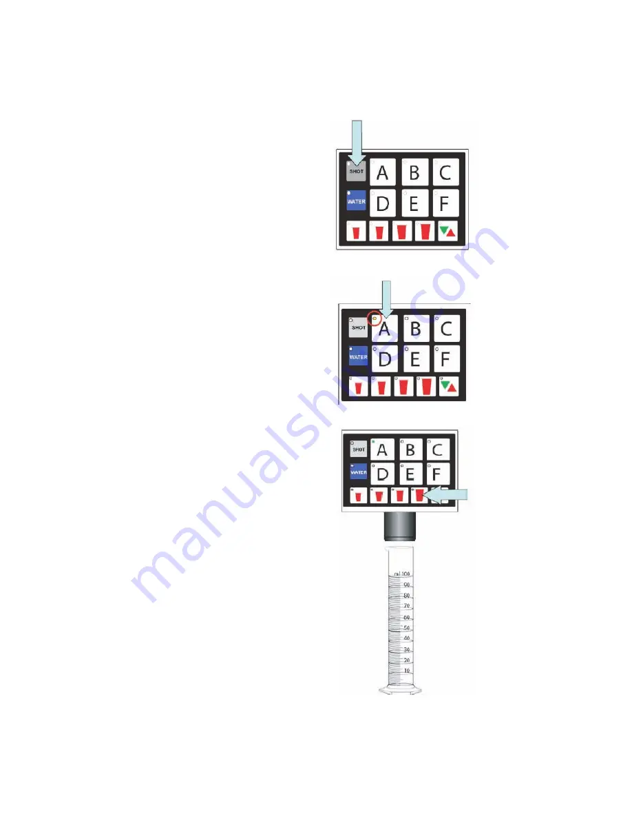
2.11 SHOT SIZE PROGRAMMING

Flavor shot portions can be adjusted using the MVU touchpad and a graduated cylinder. To adjust flavor shots:

STEP 1

While in Portion Control Programming,
press the Shot button.

Pressing the Shot button again will exit Shot
Size Programming.

STEP 2

Press a “Brand” button. The brand button
will illuminate.

NOTE:

If brand is not enabled for shot

mode, the LED light on that brand will blink
twice and turn off.

STEP 3

Place a graduated cylinder under the
nozzle.

Press and hold the XL portion button until
the portion size is achieved. Target is 30 ml
(1 0z) of syrup for an XL portion for most
customers.

The XLRG LED will blink slowly to indicate
that a new shot duration has been
programmed.

NOTE: 

The other size buttons are

proportioned automatically based on the
amount poured in XL mode:

Small = 25% of XL portion

Medium = 50% of XL portion

Large = 75% of XL portion

Summary of Contents for 23308 SERIES

Page 1: ...02 LANCER CORP 6655 Lancer Blvd San Antonio Texas 78219 To order parts call Customer Service 800 729 1500 Warranty Technical Support 800 729 1550 Email custserv lancercorp com www lancercorp com Febru...

Page 2: ...PERATION 20 2 13 FINAL ASSEMBLY 21 3 RECOMMENDED SERVICES AND MAINTENANCE 21 3 1 SCHEDULED 21 3 2 CLEANING AND SANITIZING SYSTEMS 21 3 3 CLEANING AND SANITIZING BAG IN BOX BIB SYSTEMS 22 3 4 DAILY CLE...

Page 3: ...ernal maintenance The resettable breaker switch should not be used as a substitute for unplugging the dispenser from the power source to service the unit NOTE the keyswitch does not turn off power to...

Page 4: ...ater line is run for plain water ensure that it also has a shut off valve 1 4 CARBONATOR PUMP The carbonator pump is equipped with a strainer on the inlet side A water supply containing any appreciabl...

Page 5: ...alve Close flip down the relief valve and turn on the CO2 gas 4 To fill all lines with water cycle the carbonator several times by operating the dispensing valves 5 Ensure a good flow of plain water i...

Page 6: ...t process for each valve 1 9 ADJUSTING WATER TO SYRUP RATIO BRIX FOR LEV 1 Hold the brix cup under the syrup separator and activate valve Check ratio brix 2 To obtain the proper ratio use screwdriver...

Page 7: ...er Type Off Soda Soda Off Soda Off Soda Shot On On On Off On On Virtual Brand No No No B A No No Sold Out On No Yes Yes Yes No No POSITION A B C D E F WATER SODA Water Type Plain Water Plain Water Pla...

Page 8: ...flavor shots from each of the beverage positions on the valve To enter the programming mode on the MVU and assign water type to each individual brand Carbonated or Non carb POSITION A B C D E F WATER...

Page 9: ...me to turn the water off for that valve if position is used for a flavor shot only STEP 3 Repeat this process for each brand STEP 4 Press the Pour Cancel button to lock the changes in place and exit t...

Page 10: ...ive seconds to get into programming mode STEP 2 Press the Shot button The Shot button will illuminate Brands enabled for shots will be illuminated STEP 3 Press the Brand button to turn the shot mode f...

Page 11: ...in that time frame however you can exit any time within the 60 second window by pressing Pour Cancel The changes you ve made will be saved STEP 1 Press the D and F brand buttons simultaneously for 5...

Page 12: ...is set for Sold Out the virtual brand will also be controlled by the Sold Out switch STEP 4 Select shot LED will blink quickly STEP 5 Press the Pour Cancel button to lock the changes in place and exi...

Page 13: ...slowly STEP 4 Press the Pour Cancel button to lock the changes and exit the program mode NOTE The program will save automatically in 60 seconds if no additional changes are made in that time frame ho...

Page 14: ...ule cover to expose syrup flow controls and solenoids Remove tower cap to expose the soda and plain water flow controls All active brands should have their shutoffs in the open position as illustrated...

Page 15: ...e outer nozzle and insert syrup separator Lancer PN 82 3964 01 This is important to do during flow rate check so you can determine if the separator has been properly installed NOTE Water will leak thr...

Page 16: ...TE The LED will blink twice and turn off if the brand has been programmed as a flavor shot instead of a drink You will need to reprogram the brand as a drink prior to setting the portion STEP 1 Press...

Page 17: ...ogramming NOTE The program will save automatically in 60 seconds if no additional changes are made in that time frame however you can exit any time within the 60 second window by pressing Pour Cancel...

Page 18: ...rage will pour The other brands selected will flash slowly If multi brand programming do not set carbonated drinks and non carbonated drinks at the same time because carbonated drinks tend to pour fas...

Page 19: ...E If brand is not enabled for shot mode the LED light on that brand will blink twice and turn off STEP 3 Place a graduated cylinder under the nozzle Press and hold the XL portion button until the port...

Page 20: ...NG PORTION CONTROL STEP 1 Place cup under MVU nozzle STEP 2 Press the Shot button The Shot LCD will stay illuminated active for 10 seconds STEP 3 Select Brand Button Brand will stay illuminated for up...

Page 21: ...health department guidelines to maintain proper operation and sanitization NOTE The cleaning and sanitizing procedures below pertain to the Lancer equipment identified by this manual If other equipme...

Page 22: ...e container under applicable dispensing valve Activate valve until water is dispensed Flush and rinse line and fittings for a minimum of 60 seconds to remove all traces of residual product NOTE Extend...

Page 23: ...ipe off dispensing lever 3 Wearing sanitary gloves remove drain and air dry the nozzle and diffuser 4 Wearing sanitary gloves replace diffuser twist nozzle in place 5 Connect power and replace cover V...

Page 24: ...tank by flipping up relief valve until water spurts out E Reset high pressure CO2 gas regulator to 75 PSI Change CO2 tank if required F Inspect check valve for blockage Check carbonator control Check...

Page 25: ...ply is on carbonator pump motor is connected and probe is not damaged Reset by unplugging and re plugging power supply 4 5 Pump deck LED blinking 1 blink per second A Short in probe B Short in harness...

Page 26: ...26 28 0752 02 5 ILLUSTRATIONS PARTS LISTINGS AND WIRING DIAGRAMS 5 1 ICD SERIES 23308 FREESTANDING...

Page 27: ...SL MS SS 16 51 6280 Weldment Assy Front Cover MVU 17 05 2467 Coupler Drip Tray Drain IC 18 05 2728 Drip Tray Sonic 30 CIC 19 23 1001 01 Cup Rest Wire 3023 20 30 5926 Splash Plate 3023 21 30 10302 Lid...

Page 28: ...5 25 26 26 27 27 29 29 11 11 12 12 14 14 15 15 16 16 17 17 18 18 19 19 21 21 5 5 30 30 33 33 USE TIE WRAPS USE TIE WRAPS TO TIE DOWN TO TIE DOWN INSULATION INSULATION ONTO TUBES ONTO TUBES 24 24 23 23...

Page 29: ...B B B B 16 06 3129 Label C C C C 17 06 3130 Label D D D D 18 06 3131 Label E E E E 19 06 3132 Label F F F F 20 17 0622 2 Body Assy Shutoff 2 Pack 21 19 0470 Vlv Assy 2 Pack SY SY 4 5 17 0624 1 Body A...

Page 30: ...Flavor 8 05 2766 Lock Hose HMFN 9 54 0473 Outlet Assy Water MVU 4 5 10 02 0089 O Ring 2 012 97 0999 5 4 NOZZLE HYBRID MULTI FLAVOR A B C ITEM PN DESCRIPTION 1 54 0480 Injector Assy Syrup HFMN 4 A 02 0...

Page 31: ...5 2 1 ITEM PN DESCRIPTION 1 05 2671 Body Flow Control 2 Pack 2 03 0088 02 Retainer Flow Control 3 82 0527 01 Plug Adjustment Assy Syrup Wht 4 81 0382 Sleeve Syrup Soda 4 5 oz Valve 5 81 0383 Piston S...

Page 32: ...EMBLY SOLENOID 2 PACK MVU 8 8 13 13 9 9 1 1 5 5 15 15 10 10 11 11 14 14 16 16 3 3 7 7 4 4 6 6 2 2 17 17 12 12 FRONT VIEW FRONT VIEW RETAINER PLATES AND RETAINER PLATES AND SCREWS REMOVED SCREWS REMOVE...

Page 33: ...re Assy Molded Seal VV 7 12 0364 04 01 Coil Assy LFCV 8 02 0538 O Ring 5 212 97 0999 9 10 0430 05 Plug Nut Solenoid LFCV 430C 10 81 0515 01 Bonnet Subassy SOL LFCV 11 02 0109 O Ring 2 114 97 0999 12 3...

Page 34: ...7 0999 6 03 0088 02 RETAINER FLOW CONTROL 7 03 0171 SPRING SODA FLOW CONT LEV 8 03 0180 02 SPRING CORE VV 9 03 0450 RETAINER SOLENOID CVM 10 04 0267 02 SCR 8 16X 5 PLSTI HHSW W S 11 04 0600 01 WASHER...

Page 35: ...IPTION 1 52 0931 01 Harness Assy SOS Main 2 52 3210 Harness Main Right Side MVU 3 52 3205 Harness Main Left Side MVU 4 52 3207 Harness Wire Assy Jumper 5 52 3206 Harness Assy Keyswitch 6 52 3211 Harne...

Page 36: ...36 28 0752 02 5 10 MVU...

Page 37: ...37 28 0752 02 5 11 MVU CONTROL BOARD...

Page 38: ...38 28 0752 02 5 12 POWER SUPPLY 2 2 16 16 27 27 4 4 10 10 9 9 7 7 1 1 3 3 19 19 18 18 13 13 6 6 15 15 29 29 28 28 5 5 14 14 12 12 8 8...

Page 39: ...ck Circuit Breaker 7 25 0094 Transformer Toroidal 115VA 22VAC 8 04 1412 01 Scr 1 4 20 x 2 00 HXHD 9 04 0033 01 Washer Flat 1 4 10 04 0032 01 Nut Nylock 1 4 20 12 04 0292 Scr 6 32 x 438 PH PH 13 04 029...

Page 40: ...LANCER To order parts call Customer Service 800 729 1500 Warranty Technical Support 800 729 1550 Email custserv lancercorp com www lancercorp com...

Reviews: