8
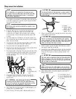
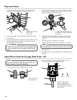
16. Route appropriate tubing from the carbonator pump inlet and
the “U” fitting at water supply then connect tubing to inlet us
-
ing flare seal washer
(PN 05-0017).
Use a back-up wrench
to prevent damage to carbonator pump.
A
B
C
A. Carbonator
B. Carb Water Inlet
C. Carb Water Line
D. Fitting
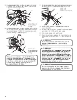
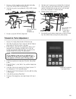
If the water source is above 65 psi (0.448 MPa), cut
tubing assembly and install Water Regulator Kit (PN
18-0253/02, sold separately)
as shown in kit instruction
sheet. Once installed, use a test gauge assembly (PN
22-0138, sold separately), to set regulator at a
maximum of 65 psi (0.448 MPa).
NOTE
A
B
A. Plain Water Line
B. Oetiker Pliers
C. Fitting
C
The dispenser must be properly electrically grounded
to avoid serious injury or fatal electrical shock. The
power cord has a three-prong grounded plug. If a
three-hole grounded electrical outlet is not available,
use an approved method to ground the unit. Follow all
local electrical codes when making connections. Each
dispenser must have a separate electrical circuit. Do
not use extension cords. Do not connect multiple
electrical devices on the same outlet.
!
WARNING
Do not use mechanical devices or other means to
accelerate the defrosting process, other than those
recommended by the manufacturer.
H
WARNING
Never energize the machine if there is any trace of
damage. Contact Lancer Customer Service for
assistance.
H
WARNING
A
B
C
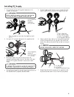
A. CO
2
Inlet
B. CO
2
Line
C. Pressure Relief Valve
17. Route appropriate tubing from the syrup pump/syrup supply
location to the CO
2
inlet and connect tubing to CO
2
inlet.
18.
Feed all tubing, power cord, and drain line through the
counter top cutout.
19. Connect tubing routed from carbonated water inlet and plain
water inlet to the “U” fitting at the water supply.
20. Turn on water supply and check for leaks.
21. Plug in the unit to a grounded electrical outlet then turn the
power switch, at the top of the unit, to begin building an ice
bank.
15. Route appropriate tubing from the plain water inlet, located
at the front of the unit, to one side of the “U” fitting at water
supply and connect tubing to inlet.
Summary of Contents for Delta-600 R-290
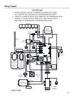
Page 23: ...23 Wiring Diagram...


