background image

1. INSTALLATION

  1.1   RECEIVING


Each unit is completely tested under operating conditions and thoroughly inspected before 


shipment. At time of shipment the carrier accepts the unit, and any claim for damage must be made 

with the carrier. Upon receiving units from the delivering carrier, carefully inspect carton for visible 

indication of damage. If damage exists, have carrier note same on bill of lading and file claim with 

carrier.

  1.2   UNPACKING
  

A.   Set shipping carton upright on the floor.


B.   Cut band and remove.


C.   Open top of carton and remove interior packing.


D.   Lift carton up and off of the dispenser.


E.   Remove wood shipping base from the bottom of the dispenser. (Support dispenser while


removing shipping base to prevent damage to the dispenser.)


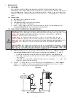
1.3   SELECTING COUNTER LOCATION (SEE FIGURE 1)


10


A.   Select a location close to a properly grounded electrical outlet, convenient to an open type    


drain, access for soda, water, and syrup lines, and sufficient clearance for air circulation.


1.   If at all possible, location should be away from direct sunlight or other heat sources.


2.   Connecting lines may be run through access in back of the unit or extend down through a

     counter 

cut 

out.


3.   The counter must support the weight of the dispenser, ice, and possibly an ice maker. Total


weight may exceed 800 lbs (363.6 kg). 


B.   Unit may be installed directly on the countertop or on legs supplied with the unit. If installed


directly on the counter, the unit must be sealed to the countertop. If an ice maker is to be


mounted on top of dispenser, do not install dispenser on legs.

FIGURE 1. 

SUFFICIENT CLEARANCE FOR

34" (864 mm)

9 3/4" (248 mm)

AIR

IN

AIR

IN

MINIMUM of 6" (152 mm)

MINIMUM OF 6" (152 mm)

30 1/2" (775 mm)

30 1/2" (775 mm)

WIDTH OF THE 85-4562H DISPENSER IS 44" (1118 mm) 

FILLING MANUALLY WITH ICE,
WHEN ICE MAKER NOT USED

DISPENSE HEIGHT

CLEARANCE ABOVE ICE MAKER

W

ALL

 CLEARANCE

!

WARNING

 THIS APPLIANCE MUST BE EARTHED. THIS DISPENSER MUST BE ELECTRICALLY GROUNDED TO 

AVOID DANGER TO THE OPERATOR. THE POWER CORD PROVIDED HAS A THREE PRONG GROUNDED PLUG. IF 

A THREE HOLE GROUNDED ELECTRICAL OUTLET IS NOT AVAILABLE, USE AN APPROVED METHOD OF 

INSURING A PROPER GROUND TO THE DISPENSER.

ADVERTENCIA 

 ESTE APARATO DEBE CONECTARSE A TIERRA. ESTE DISPENSADOR DEBE TENER 

CONEXIÓN A TIERRA PARA EVITAR PELIGRO PARA EL OPERADOR. EL CABLE SUMINISTRADO TIENE UN 

ENCHUFE DE TIERRA DE TRES PUNTAS. SI UN AGUJERO TRES TOMACORRIENTE PUESTO A TIERRA NO ESTÁ 

DISPONIBLE, UTILICE UN MÉTODO APROBADO DE ASEGURAR UNA TIERRA CORRESPONDIENTE EN LA 

CUBETA.

AVERTISSEMENT

 CET APPAREIL DOIT ETRE MIS A LA TERRE. CE DISTRIBUTEUR DOIT ÊTRE MIS À LA TERRE 

ÉLECTRIQUE POUR ÉVITER DANGER POUR L’OPÉRATEUR. LE CORDON D’ALIMENTATION FOURNIS A UN TROIS 

BROCHES TERRE. SI UN TROIS TROUS TERRE ALIMENTATION ÉLECTRIQUE N’EST DISPONIBLE, UTILISER UNE 

MÉTHODE APPROUVÉE D’ASSURER UN MOTIF VALABLE AU DISTRIBUTEUR.

Summary of Contents for IBD44 Series

Page 1: ...ranty 800 729 1550 custserv lancercorp com lancercorp com Manual PN 28 0420 02 FEBRUARY 2006 FOR QUALIFIED INSTALLER ONLY ICE BEVERAGE DISPENSERS IBD44 SERIES 4500 Operation Manual PN 28 0420 02 Lance...

Page 2: ...2 3 DAILY CLEANING 12 2 4 ICE BIN CLEANING STARTUP AND MONTHLY 13 2 5 CLEANING AND SANITIZING BEVERAGE COMPONENTS FIGAL SYSTEMS 13 14 2 6 CLEANING AND SANITIZING BEVERAGE COMPONENTS BAG IN BOX SYSTEMS...

Page 3: ...ONATION 19 4 LIGHT EMITTING DIODES LEDS 20 5 AUTOMATIC AGITATION AND LOW ICE ALARM CONTROL 20 21 6 ILLUSTRATIONS AND PARTS LISTINGS 22 6 1 DECALS AND LABELS 22 23 6 2 FINAL ASSEMBLY POST MIX IBD AND I...

Page 4: ...115V 60Hz 6 amps WEIGHT Shipping 460 lbs 129 3 kg Empty 400 lbs 113 4 kg ICE Capacity 360 lbs 95 2 kg Dispensable 300 lbs 77 1 kg FITTINGS Soda water inlet 3 8 barb Brand syrup inlets 3 8 barb PLAIN...

Page 5: ...nded electrical outlet Enough space to install the dispenser Include space for a top mounted ice machine if necessary Does the top mounted ice machine have a minimum clearance on all sides Located awa...

Page 6: ...ni os sin supervisi n Esta unidad no ha sido dise ada para suministrar productos l cteos La temperatura ambiente operativa m nima m xima para el dispensador es de 40 F a 105 F 4 4 C a 40 5 C No opere...

Page 7: ...del agua de red Minimo 25 PSIG 0 172 MPA Maximo 50 PSIG 0 345 MPA En unidades sin regulador de presi n incorporado si la presi n del agua es superior a 50 PSIG 0 345 MPA se debe usar un regulador de...

Page 8: ...ques locaux lorsque vous faites des connexions Chaque distributrice doit avoir un circuit lectrique s par N utilisez pas de cordons prolongateurs avec cet appareil Ne pas le brancher avec d autres app...

Page 9: ...nd local standards It is the responsibility of the installer to ensure compliance Proporcione un suministro adecuado de agua potable La l nea de suministro de agua debe ser de una tuber a de por lo me...

Page 10: ...installed directly on the countertop or on legs supplied with the unit If installed directly on the counter the unit must be sealed to the countertop If an ice maker is to be mounted on top of dispens...

Page 11: ...d electrical outlet J Test Motor operation by pushing Ice Chute K Clean and sanitize dispenser see Section 2 L Fill unit approximately half full with ice Push Chute and check for ice delivery M Finish...

Page 12: ...f five 5 gallons of cleaning mixture should be prepared Any equivalent cleanser may be used as long as it provides a caustic based non perfumed easily rinsed mixture containing at least two 2 percent...

Page 13: ...er is dispensed Flush and rinse line and fittings for a minimum of 60 seconds to remove all traces of residual product 13 D Disconnect CO2 supply hose from the water filled syrup tank E Following the...

Page 14: ...sidual product D Following the instructions as described in 3 1 above mix appropriate amount of cleaning solution in a clean container Place syrup inlet line in container filled with cleaning solution...

Page 15: ...supply F Magnet not in ice chute shell A Connect dispenser to power source B Replace ice chute base C Plug in wiring harness D Replace PC board E Check voltage to power supply Check fuses F Install m...

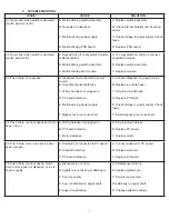
Page 16: ...da flow control A Verify incoming CO2 pressure is between 70 75 PSI B Open shutoff fully C Remove soda flow control from valve and clean out any foreign material to ensure smooth spool movement 3 12 I...

Page 17: ...aking at connections A Loose water connections B Flare seal washer leaks A Tighten water connections B Replace flare seal washer 3 17 Water only dispensed no syrup Or syrup only dispensed no water A S...

Page 18: ...with ice and allow coldplate to re stabilize B Correct prior to dispenser C Adjust CO2 pressure downward but not less than 70 PSI D Re adjust and reset ratio E Remove and clean F Bleed air from BIB li...

Page 19: ...e defective pump 3 24 BIB pump fails to restart after bag replacement A BIB connector not on tightly B BIB connector is stopped up C Kinks in syrup line A Tighten BIB connector B Clean out or replace...

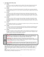
Page 20: ...Replace if defective 4 7 LED D9 This light is on when the motor is activated When the chute is depressed this light should turn on If it does not check to see if the motor harness is connected to the...

Page 21: ...ring to the table and setting the switches as shown ON times from one 1 second to four 4 seconds in one 1 second increments can be obtained EXAMPLE For three 3 seconds ON time switch 3 should be in th...

Page 22: ...GS AND WIRING DIAGRAMS 6 1 DECALS AND LABELS 7 DA NG ER HAZ ARD OUS MOV ING PAR TS SER VICIN G OR CLEA NING UNIT DISC ONN ECT POW ER BEFO RE UNIT MAY ACTI VATE UNE XPEC TEDL Y ELE CTR ICAL SHO CK HAZ...

Page 23: ...ing Diagram IBD44 5 06 1207 Label Cold Plate Cleaning IBD 6 06 1522 Label Low Ice IBD 7 06 1139 Label Warning Lid IBD 8 06 1457 01 Panel Graphics Coca Cola IBD44 9 06 2058 01 Decal Wrapper Side Coca C...

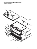
Page 24: ...6 2 FINAL ASSEMBLY POST MIX IBD AND ICE DISPENSER 5 3 5 7 4 2 3 4 6 1 9 8 11 10 12 13 14 15 17 16 18 19 20 21 22 23 24 24...

Page 25: ...r IBD 12 30 7343 01 Splash Plate IBD44 Units manufactured before December 2003 30 8635 Splash Plate IBD44 Units manufactured after December 2003 13 03 0300 Clip Wire Adhesive IBD 14 03 0049 Clip Cord...

Page 26: ...P TIE WRAP BLACK BLACK TIE WRAP TO TRANSFORMER TO KEYSW ITCH W H IT E BLAC K TIE WRAP TIE WRAP BLAC K BLACK TIE WRAP TO TRANSFORMER TO KEYSWITCH 5 7 19 6 8 9 10 4 3 11 12 13 26 6 3 FAUCET PLATE AND IC...

Page 27: ...C 04 0327 Washer Flat R D 12 0195 Solenoid D 90 R E 30 5165 01 Bracket Solenoid R F 23 1380 Plunger Assy R G 10 0496 Pin Solenoid Assy R H 03 0110 Spring Solenoid R I 03 0111 Ring Retaining 5133 62 R...

Page 28: ...TOR SUB ASSEMBLY POST MIX 1 2 2 3 19 22 7 8 8 9 21 4 10 10 11 12 13 14 15 16 15 16 17 15 18 19 20 5 5 4 19 19 32 30 31 FROM RED LEADS ON BALLAST FROM BLUE LEADS ON BALLAST 26 TO YELLOW LEADS ON BALLAS...

Page 29: ...P IBD Left Side 18 30 6679 Bracket Merchandiser Support IBD44 19 04 0504 Screw 8 18 x 0 375 PHD 20 52 2181 01 Ballast Assy 120V IBD44 21 51 5836 Wrapper Sub Assy Right Side IBD44 22 12 0097 Switch Key...

Page 30: ...R MOTOR VALVE VALVE KEY SWITCH SWITCH KEY DISPENSE SWITCH SWITCH DISPENSE LOW ICE LIGHT LOW ICE LIGHT ELECTRICAL BOX BOUNDARY WHITE BLACK WHITE J3 J7 WHITE BLACK BLACK WHITE BLACK BLACK WHITE BLACK BL...

Page 31: ...SWITCH IS CLOSED D9 ON WHEN MOTOR IS ON D8 ON WHEN TRAP DOOR SOLENOID IS OPEN D7 FLASHES WHEN ICE IS LOW D6 ON WHEN 32VDC IS AVAILABLE D5 ON WHEN 5VDC IS AVAILABLE D4 ON WHEN LID IS CLOSED LED INDICAT...

Page 32: ...Lancer Corp 800 729 1500 Technical Support Warranty 800 729 1550 custserv lancercorp com lancercorp com...

Reviews: