11
1.3 SELECTING COUNTER LOCATION
(CONTINUED)
NOTE:
Water pipe connections and fixtures directly connected to a potable water supply must all be
sized, installed, and maintained according to Federal, State, and Local laws. The water supply must
be protected by means of an air gap, a backflow prevention device (located upstream of the CO2
injection system) or another approved method to comply with NSF standards. A backflow
prevention device must comply with ASSE and local standards. It is the responsibility of the installer
to ensure compliance.
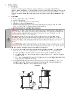
C. Location must insure sufficient clearance on sides, top and back of unit is provided for
ventilation and air circulation (see Figure 1).
D. Additionally, if an ice maker is not top mounted on the unit, sufficient clearance should be
provided [a minimum of 16 inches (40.6 cm) is recommended] to allow filling the unit with ice
from a five (5) gallon (19 liter) container (see Figure 1).
1.4 INSTALLING THE DISPENSER
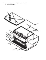
A. Remove Cup Rest, Drip Tray, Splash Plate, and Top Cover.
B. Remove Cover Plate at rear of unit if not a through the counter installation.
C. Connect soda and water supply lines to 3/8 inch barb fittings at the front of the unit. Check for
leaks. (If dispenser is to operate with all soda valves, connect water line into one of the soda
supply lines.)
D. Connect syrup supply lines to the 3/8 inch barb inlet fittings at the front of the unit. Check for
leaks.
E. Uncoil drain hose from Cold Plate drain and extend to an open type drain.
F. Install Drip Tray and extend hose to open type drain.
G. Both drain lines must be insulated with a closed cell insulation. Insulation must cover the entire
length of the drain hose, including fittings. The drain should be installed in such a manner that
water does not collect in sags or other low points, as condensation will form.
H. Install Cup Rest and Splash Plate.
I. Connect Power Cord to grounded electrical outlet.
J. Test Motor operation by pushing Ice Chute.
K. Clean and sanitize dispenser (see Section 2).
L. Fill unit approximately half full with ice. Push Chute and check for ice delivery.
M. Finish filling unit with ice.
N. Install Top Cover.
NOTE:
Lancer does not recommend the use of shaved, flake, nugget, or pellet ice in dispensers not
properly equipped to do so.
O. Set brix ratio for beverage dispensing valves according to manufacturer’s instructions.
!
WARNING
WHEN INSTALLING AN ICEMAKER ON AN IBD UNIT, A BIN THERMOSTAT OR OTHER MEANS
OF CONTROLLING THE ICE LEVEL MUST BE INSTALLED. FAILURE TO DO SO COULD RESULT IN DAMAGE TO
THE DISPENSING MECHANISM AND VOID THE WARRANTY. DURING THE AUTOMATIC AGITATION CYCLE AND/OR
WHILE DISPENSING ICE, THERE MUST BE ADEQUATE ROOM BETWEEN THE TOP OF THE ICE LEVEL AND THE
BOTTOM OF THE ICEMAKER SO THAT THE ICE CAN MOVE WITHOUT OBSTRUCTION. CONTACT YOUR
ICEMAKER SUPPLIER FOR INFORMATION ON PROPER BIN THERMOSTAT.
ADVERTENCIA
AL INSTALAR UNA MÁQUINA DE HIELO EN UNA UNIDAD DE IBD, A BIN TERMOSTATO U OTROS
MEDIOS DE CONTROLAR EL NIVEL ICE DEBE ESTAR INSTALADO. NO HACERLO PUEDE CAUSAR
DAÑOS AL MECANISMO DISPENSING Y ANULAR LA GARANTÍA. DURANTE EL CICLO AUTOMÁTICO AGITACIÓN Y
/ O HIELO, MIENTRAS QUE LA DISPENSACIÓN, DEBE HABER ESPACIO SUFICIENTE ENTRE EL TOP DEL NIVEL
DE HIELO Y EL FONDO DE LA MÁQUINA DE HIELO PARA QUE EL ICE PUEDE MOVERSE SIN OBSTRUCCIÓN.
CONTACTO CON SU PROVEEDOR DE FABRICACIÓN DE HIELO PARA INFORMACIÓN SOBRE ADECUADO BIN
TERMOSTATO.
AVERTISSEMENT
LORSQUE VOUS INSTALLEZ UNE MACHINE À GLAÇONS SUR UNE UNITÉ EIA, UN
THERMOSTAT DU BAC OU AUTRES MOYENS DE CONTRÔLER LE NIVEAU DE LA CIE DOIT ÊTRE INSTALLÉ.
PANNE DE LE FAIRE POURRAIT PROVOQUER DES DOMMAGES AU MÉCANISME DE DISTRIBUTION ET ANNULE
LA GARANTIE. PENDANT LE CYCLE AUTOMATIQUE AGITATION ET / OU TOUT DISTRIBUTION DE GLACE,
DOIVENT TROUVER PLACE SUFFISANTE ENTRE LE SOMMET DE L’ÉCHELLE DE L’ICE ET LE BAS DE LA
MACHINE À GLAÇONS POUR QUE LA GLACE PEUT SE DÉPLACER SANS ENTRAVE. CONTACTEZ VOTRE
FOURNISSEUR DE ICEMAKER INFORMATIONS SUR UNE BONNE THERMOSTAT DU BAC.


