Page 43
What to do after "humidity fault"?
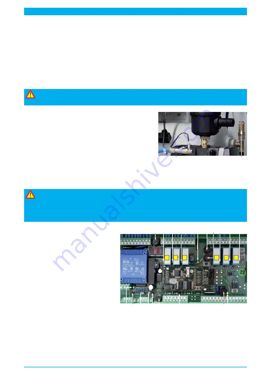
The MFR (
45
) switched off the compressor (
8
), the humidity of the output air is inadmissibly high.
• The red signal-LED „
F
“ (
48
) illuminates on the MFR
and the red signal-LED „
Fault / Fel“
(
20
) on the instrument panel (
2
) illuminates.
• The red signal output-LED „
A
“ (
59
) illuminates on the MFR
• The ACS shows a humidity value of the output air that is inadmissible high (> 4%).
1. Search for faults, remedy faults
according to charts "Causes and remedying of faults", page 42.
2. Restart equipment and allow to run dry
Deadly risk!
Electro specialists only are allowed to operate the buttons of the MFR.
Other users have to use the ACS device (18).
• Open safety valve "high pressure" (
29
).
• Press button „
F-Off
“ (
61
) on the MFR (
45
) or ACS (
18
).
•
The compressor starts.
•
The green Signal-LED „
F-on
“ (
52
) in the MFR is turned off
= no humidity monitoring.
• The red Signal-LED „
F
“ (
48
) illuminates in the MFR
= pressurised air humidity is unadmissibly high.
29
After a while
• The red Signal-LED „
F
“ (
48
) on the MFR turns off = the pressurised air is dry.
•
The green Signal-LED „
F-on
“ (
52
) on the MFR is still turned off = no humidity monitoring.
Warning!
Pressing the button „F-off“ overrides the humidity monitoring.
The button must be used only, if a fault occurred, the „high pressure“ safety valve (29) is open
and the shut-off valve "cable pressure" is shut.
Humidity monitoring must be reactivated immediatly after trouble-shooting, to assure proper
function of the pressurisation equipment.
In order to get immediate humidity moni-
toring, the "F-off" operation must be
overridden:
• Press button „F-Off“ (
61
) of the MFR or of
the ACS for approx. 5 seconds.
• The green LEDs „F-On“ (
52
) on the MFR
illuminate again.
• Close safety valve "high pressure" (
29
).
• Then carry out function testing.
MFR
The humidity monitoring activates itself automatically after approx. 2 operating hours of the compres-
sor, if the „F-off“ operaton is not determined manually.
Switching the motor protective switch (
43
) off and on again, terminates the „F-off“ operation also. This proce-
dure resets the MFR by breaking its power supply.
A
54
55
56
57
63
62
58
59
60
50
51
48
52 53
61
49
B 47
KY1
KY2
KK1
K-W
K-A
K-N
Summary of Contents for RTS 1000
Page 15: ...Page 15 39 35 37 36 36 23 42 28 27 24 6 33 38 40 41 32 22 29 25 8...
Page 21: ...Page 21...
Page 47: ...Page 47 7 16 14 15 15 18 17 13 20 24 8 23 10 6 9 4 22 21 19 8...
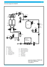
Page 51: ...Page 51 Pneumatics diagram Nr 074891 000...
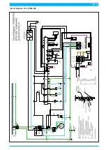
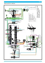
Page 53: ...Page 53 Circuit diagram Nr 074880 000...


