Page 6
NIR Borescope
Thermal Imaging System
Installation Guide
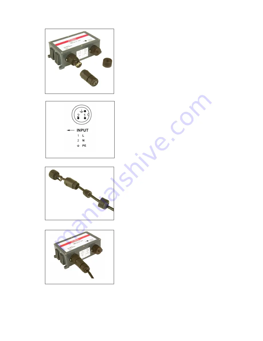
Fig. 3-4
Fig. 3-6
The connection terminals inside the input connector
will now be revealed (Fig. 3-4).
4)
Unscrew the connector front section from
the Power Supply Unit and disassemble the
remaining parts of the connector.
5)
Slide the rear locking ring, gasket and shell
body over the mains input cable.
6)
Strip back the mains cable wires to the
appropriate lengths and connect them to the
Input
connector terminals (Fig. 3-5) as per
the wiring schedule below:
Pin 1 = Live
Pin 2 = Neutral
Pin 3 = N/C
E = Earth
7)
The mains input cable connector is now ready
for re-assembly and connection to the Power
Supply Unit (Fig. 3-6). Re-assemble the mains
input connector.
Fig. 3-5
Fig. 3-7
8)
Attach the mains cable to the Input connector
of the Power Supply Unit (Fig. 3-7).
Summary of Contents for NIR Borescope
Page 4: ......


