17
Section 1: Assembly and Set-Up
8/15/12
RCR3596, RCRM3596, RCR3510 & RCRM3510 Rotary Cutters 312-517M
Table of Contents
3-Point Hook-Up
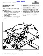
Refer to Figure 1-9 on page 15:
!
DANGER
A Crushing Hazard exists when hooking-up equipment to a
tractor. Do not allow anyone to stand between tractor and
implement while backing-up to implement. Do not operate
hydraulic 3-Point lift controls while someone is directly
behind tractor or near implement.
!
WARNING
Always disengage PTO, engage parking brake, shut off
tractor, remove ignition key, and wait for all moving parts to
come to a complete stop before dismounting from tractor.
1.
Locate the cutter on a flat level surface.
2.
Determine the hitch category of the tractor that will
be used:
a. Category I tractors will have a lower hitch link
hole diameter of 7/8". The top link hole diameter
(cutter end) will be 3/4".
b. Category II tractors will have a lower hitch link
hole diameter of 1 1/8". The top link hole diameter
(cutter end) will be 1".
c. Category III tractors will have a lower hitch link
hole diameter of 1 7/16". The top link hole
diameter (cutter end) will be 1 5/16".
Refer to Figure 1-9 on page 15:
3.
Remove lower linch pins (#3) and hitch pins (#1) from
the deck. Remove upper cotter pin, flat washer and
hitch pin (#5) from the deck.
4.
Slowly back tractor up to the cutter while using the
tractor’s 3-point hydraulic control to adjust the lower
link arms up or down to match the tractor’s lower arm
pin holes to the cutter hitch pin holes. The lower lift
arms of a Category 2 tractor will be positioned to the
outside of the cutters lower hitch lugs on RCR35596
& RCRM35596 cutters.
5.
Insert hitch pins (#1) and secure with linch pins (#3).
6.
Connect the top link (#4) to the upper pivot hitch
using 1" clevis pin (#5), washer and cotter pin
supplied. Bend cotter pin after inserting to prevent it
from falling out.
7.
The lift link rods on your tractor’s 3- point hitch should
be adjusted to allow for lateral float. Please consult
you tractor’s manual for adjusting instructions.
Driveline Installation
!
DANGER
Do not engage tractor PTO while hooking-up and unhooking
driveline or while someone is standing near the driveline. A
person’s body and/or clothing can become entangled in the
driveline resulting in serious injury or death.
!
DANGER
All guards and shields must be installed and in good working
condition at all times during cutter operation.
!
WARNING
Always disengage PTO, engage parking brake, shut tractor
engine off, remove switch key, and wait for blades to come to
a complete stop before dismounting tractor.
!
WARNING
Do not over-speed PTO or machine breakage may result.
Some tractors are equipped with multispeed PTO ranges. Be
certain your tractor’s PTO is set for the cutter’s rated PTO
speed. See Specifications & Capacities for rated PTO speed.
!
WARNING
Do not use a PTO adaptor with a quick hitch. A PTO adapter
will increase strain on the tractor’s PTO shaft resulting in
possible damage to shaft and driveline.
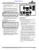
1.
Park tractor on a level surface. Slowly engage tractor
3-point lift lever to raise cutter until gearbox shaft is in
line (level) with tractor PTO shaft.
2.
Support cutter deck at this height with support jacks
or blocks to keep cutter from drifting down.
3.
Place gear selector in park, set park brake, shut
tractor off and remove switch key.
4.
Remove rubber protective sleeve from gearbox input
shaft and discard.
5.
Unsnap one end of gearbox shield access doors and
rotate doors open.
6.
Attach slip-clutch end of driveline (#16) to gearbox
input shaft. Make certain that the slip-clutch is fully
onto the shaft splines. Tighten conical dog pin on
back side of slip-clutch to 45-50 ft-lb torque.
IMPORTANT: An additional driveline may be
required if cutter is to be used on more than one
tractor, especially if a Quick Hitch is used.
The driveline must be lubricated before putting it into
service. Refer to “Lubrication” on page 35.
The tractor’s PTO shaft and cutter gearbox shaft
must be aligned and level with each other during
installation of driveline.


