background image

Assembly Instructions

7/8/20

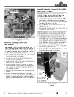
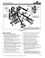
Third Function Valve Kit #380-340A Installation Instructions Manual No. 380-151M   

4

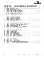
Control Lever Assembly

Refer to Figure 3 on page 3, & Figure 4:

1. Remove existing knob (not shown) from end of 

control lever “D”.

2. Install new control handle (#17) onto control lever (D). 

Adjust control handle to align the push buttons to suit 

the operator and then tighten set screws (#6) against 

control lever. Tighten jam nuts (#8) to secure set 

screws (#6).

3. Thread wiring harness (#18) through hole “E” and 

forward under the tractor platform.

Refer to Figure 3 on page 3:

4.

Reference Connections “A”:

 Connect one 

black wire in harness (#18) to one black wire in 

harness (#41) and the other black wire in 

harness (#18) to one white wire in harness (#41). 

5.

Reference Connection “B”:

 Connect the two red 

wires from control handle (#17) to wire (#42) on one 

end of fuse holder (#19). 

6. Connect wire (#42) on opposite end of fuse 

holder (#19) to the positive (+) post on the tractor 

battery.

Refer to Figure 4:

7.

Secure wire harness (#18) with cable ties (#5) as 

needed.

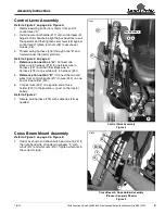
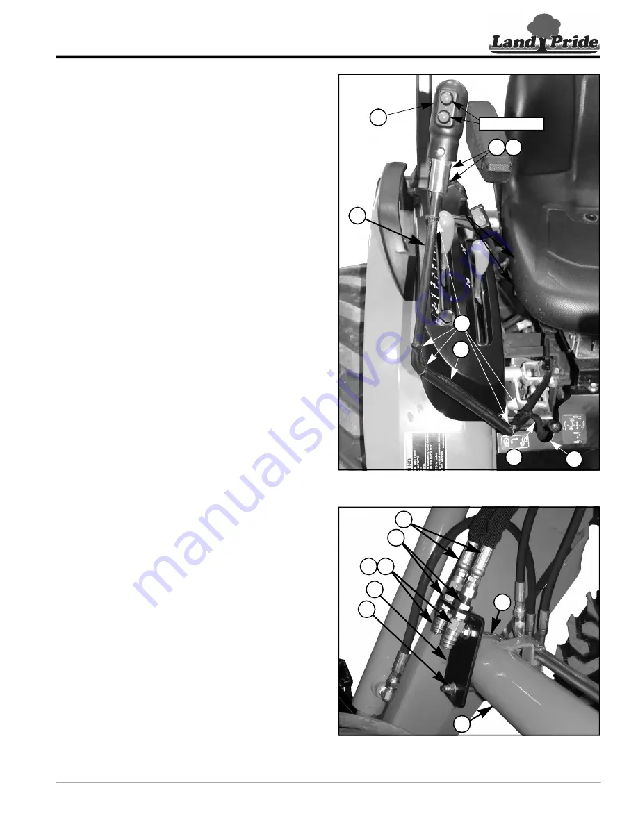
Cross Beam Mount Assembly

Refer to Figure 3 on page 3, & Figure 5:

1. Orient as shown and attach bulk head mount (#2) to 

the right-hand side of loader crossbeam “F” with 

u-bolt (#12) and whiz nuts (#10). Tighten whiz nuts to 

the correct torque.


Control Stick Assembly

Figure 4

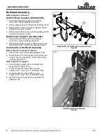
Cross Beam & Hose Holder Assembly 

(Pioneer Couplers Shown)

Figure 5

17

6

8

D

E

18

Push Buttons 

74502

5

18

2

12

10

24

F

37029

33

40

39

Summary of Contents for 380-340A

Page 1: ...Use the list that is for your specific Third Function Valve Kit as a checklist to inventory parts received Please contact your local Land Pride dealer for any missing hardware Direction Reference All...

Page 2: ...d port and return to tank port Improper hook up could cause damage to your tractor and or Third Function Valve Install Hydraulic Hoses 16 22 Refer to Figure 3 on page 3 1 Locate power beyond port on t...

Page 3: ...d level Valve Assembly Refer to Figure 2 on page 2 Figure 3 1 Bolt valve offset bracket 38 to valve mount 1 using 1 4 20 x 1 bolts 25 and whiz nuts 27 Tighten whiz nuts to the correct torque 2 Install...

Page 4: ...ack wire in harness 18 to one black wire in harness 41 and the other black wire in harness 18 to one white wire in harness 41 5 Reference Connection B Connect the two red wires from control handle 17...

Page 5: ...Tighten bulkhead locknuts 2 Attach male pioneer couplers 39 40 to bulk head fittings 33 Tighten and secure couplers Continuation of Bulkhead Assembly Refer to Figure 5 on page 4 Figure 7 1 Attach hos...

Page 6: ...he third function hydraulics using the push buttons on the newly installed control handle The top red button switch will actuate the attachment in one direction The bottom red button switch will actua...

Page 7: ...t No Description Qty 1 801 091C CRPHMS 6 32X5 8 SS 3 2 837 053C COVER PUSH BUTTON CNTRL HNDL 1 3 837 054C BASE PUSH BUTTON CNTRL HNDL 1 4 833 739C SWITCH P9 PB NO SPST MOM RED 2 5 804 054C WASHER LOCK...

Page 8: ...ns Manual No 380 151M 7 8 20 Third Function Valve Kit for Cab Tractor Figure 9 73121 851 350C 24 811 253C 16 841 563C 22 Hydraulic Hose Identification Chart 73128 Adapters 20 with Kit 380 340A only Fl...

Page 9: ...2 9 16FJIC 1 17 380 165S ASY PUSH BUTTON CNTRL HNDL See Breakdown on page 7 1 18 861 543C CP 3 4FORB QD FML FLATFACE With Kit 380 340A only 1 18 841 467C CP 9 16 FORB QD 1 4 BODY With Kit 380 149A onl...

Page 10: ...Corporate Office P O Box 5060 Salina Kansas 67402 5060 USA www landpride com...

Reviews: