
Assembly Instructions
7/8/20
Third Function Valve Kit #380-340A Installation Instructions Manual No. 380-151M
7
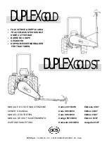
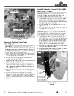
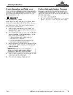
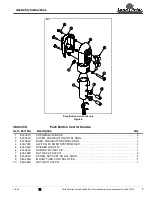
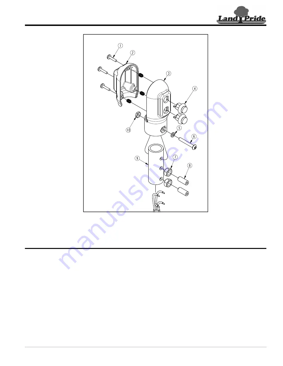
Push Button Control Handle
Figure 8
380-345S
Push Button Control Handle
Item Part No.
Description
Qty
1
801-091C
CRPHMS 6-32X5/8 SS . . . . . . . . . . . . . . . . . . . . . . . . . . . . . . . . . . . . . . . . . . . . . . . . . . . . 3
2
837-053C
COVER, PUSH BUTTON CNTRL HNDL. . . . . . . . . . . . . . . . . . . . . . . . . . . . . . . . . . . . . . . 1
3
837-054C
BASE, PUSH BUTTON CNTRL HNDL . . . . . . . . . . . . . . . . . . . . . . . . . . . . . . . . . . . . . . . . 1
4
833-739C
SWITCH, P9 PB NO SPST MOM RED . . . . . . . . . . . . . . . . . . . . . . . . . . . . . . . . . . . . . . . . 2
5
804-054C
WASHER LOCK #10 . . . . . . . . . . . . . . . . . . . . . . . . . . . . . . . . . . . . . . . . . . . . . . . . . . . . . . 1
6
801-250C
HSBHCS #10-32X1 3/8. . . . . . . . . . . . . . . . . . . . . . . . . . . . . . . . . . . . . . . . . . . . . . . . . . . . 1
7
803-008C
NUT HEX 5/16-18 PLT . . . . . . . . . . . . . . . . . . . . . . . . . . . . . . . . . . . . . . . . . . . . . . . . . . . . 2
8
801-204C
SCREW SET SCKT HD 5/16-18X3/4 . . . . . . . . . . . . . . . . . . . . . . . . . . . . . . . . . . . . . . . . . 2
9
380-225D
MOUNT TUBE, CONTROL STICK . . . . . . . . . . . . . . . . . . . . . . . . . . . . . . . . . . . . . . . . . . . 1
10
803-269C
NUT HEX 10-32 PLT . . . . . . . . . . . . . . . . . . . . . . . . . . . . . . . . . . . . . . . . . . . . . . . . . . . . . . 1
73015