background image

10

Section 1: Assembly and Set-up

FDR3590 Rear Discharge Grooming Mowers   310-229M

12/10/07

Land Pride

Table of Contents

3.

Slide tractor outer driveline universal joint over the
tractor’s splined driveline shaft. Secure with driveline
yoke locking device. Skip to step 5 if driveline fits
between tractor and implement.

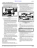
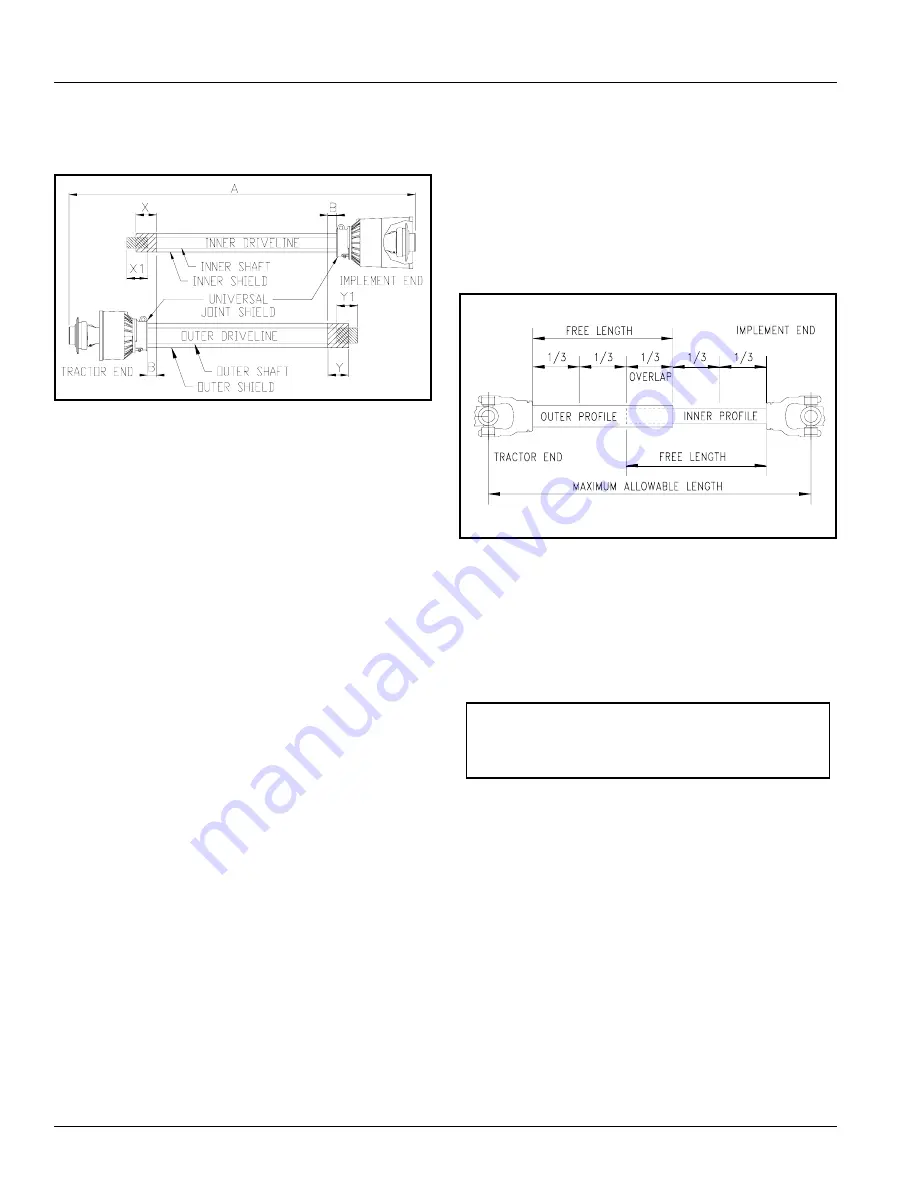
Driveline Shortening

Figure 1-4

4.

The driveline will require shortening if it is too long.
Shorten driveline as follows:

a. Raise 3-point lower arms until Grooming Mower

and tractor PTO shafts are approximately level
with each other. Securely block Grooming Mower
frame in this position. Set tractor in park, shut
tractor engine off, set park brake and remove
switch key.

b. Pull driveline apart into two sections as shown in

Figure 1-4. Attach outer driveline universal joint to
the tractor PTO shaft and inner driveline universal
joint to the Grooming Mower gearbox shaft. Pull
on each driveline section to be sure the universal
joints are secured to the shafts.

c. Hold driveline sections parallel to each other to

determine if they are too long. The inner and outer
shields on each section should end approximately
1" short of reaching the universal joint shield on
the adjacent section (see “B” dimension). If they
are too long, measure 1" (“B” dimension) back
from the universal joint shield and make a mark at
this location on the inner and outer driveline
shields.

d. Cut off the inner shield at the mark (“X

dimension). Cut the same amount off the inner
shaft (“X1” dimension). Repeat cut off procedure
(“Y” & “Y1” dimensions) to the outer driveline half.

e. Remove all burrs and cuttings.

Checking Driveline Maximum Length

Make sure you check “Checking Driveline Minimum
Length” on page 9 before checking Checking Driveline
Maximum Length.

Refer to Figure 1-5

The driveline maximum length must, when fully
extended, have a minimum overlap of the profile tubes by

22009

not less than 1/3 the free length with both inner and outer
profile tubes being of equal length.

1.

Apply multi-purpose grease to the inside of the outer
shaft and reassemble the driveline.

2.

Assemble the two driveline profiles together with just
1/3 overlapping of the profile tubes as shown in
Figure 1-5. Measure and record this overall length for
checking driveline length in step 9 below.

3.

Attach inner driveline yoke end to the Grooming
Mower gearbox input shaft.

Driveline Maximum Length

Figure 1-5

4.

Attach outer driveline yoke end to the tractor's PTO
shaft.

5.

The driveline should now be moved back and forth to
insure that both ends are secured to the tractor and
Grooming Mower PTO shafts. Reattach any end that
is loose.

6.

Hook driveline safety chain in the hole in the inner
driveline guard. Attach the other end to the
Grooming Mower’s main frame.

7.

Start tractor and raise Grooming Mower just enough
to remove blocks.

8.

Slowly engage the tractor’s hydraulic 3-point to lower
the Grooming Mower. Check for sufficient drawbar
clearance. Move drawbar ahead, aside or remove if
required.

9.

Raise and lower implement to find maximum
extended driveline length. Check to make certain
that the driveline overall length does not extend
beyond the maximum recorded length in step 2
above.

24513

Outer Shielding has been removed for clarity.

IMPORTANT: A small chain is supplied with the
driveline. This chain must be attached to the inner
driveline shield and to the Grooming Mower to
restrict shield rotation.

Summary of Contents for FDR3590

Page 1: ...d Read the Operator s manual entirely When you see this symbol the subsequent instructions and warnings are serious follow without exception Your life and the lives of others depend on it Table of Con...

Page 2: ...7 Serial Number Plate 7 Further Assistance 7 Section 1 Assembly and Set up 8 Tractor Requirements 8 Upper Hitch Arms 8 Gauge Wheels 8 Tractor Hook Up 9 PTO Hookup 9 Checking Driveline Minimum Length 9...

Page 3: ...a potential hazard to personal safety involved and extra safety precaution must be taken When you see this symbol be alert and carefully read the message that follows it In addition to design and con...

Page 4: ...hazard when driven on public roads They are difficult to see especially at night Flashing warning lights and turn signals are recommended whenever driving on public roads Use lights and devices provi...

Page 5: ...aring protection such as earmuffs or earplugs Operating equipment safely requires the full attention of the operator Avoid wearing radio headphones while operating machinery Avoid High Pressure Fluids...

Page 6: ...ur dealer locator at landpride com 3 Some new equipment installed during repair requires safety labels to be affixed to the replaced component as 818 130C Caution 13304 818 229C Amber Reflector 15947...

Page 7: ...12 10 07 FDR3590 Rear Discharge Grooming Mowers 310 229M Land Pride Table of Contents 818 556C Danger Thrown Object 818 555C Danger Rotating Blade 15945 15945 818 142C Danger Rotating Driveline 15944...

Page 8: ...FDR3590 Rear Discharge Grooming Mowers 310 229M 12 10 07 Land Pride Table of Contents 818 558C Warning General Safety 15943 818 540C Danger Guard Missing 13314 818 552C Danger Rotating Driveline ROTA...

Page 9: ...uality materials Proper assembly maintenance and safe operating practices will help you get years of satisfactory use from the machine Application The Land Pride FDR3590 Rear Discharge Grooming Mowers...

Page 10: ...ashers 5 and hex nuts 6 NOTE In order to maintain steering control ballast may need to be added to your tractor To determine whether or not to add the ballast refer to your tractors operator manual 4...

Page 11: ...during operation 15948 Upper Floating Hitch Lower Hitch Clevis Gauge Wheel Maximum PTO driveline Movement During Operation Figure 1 3 Checking Driveline Minimum Length Refer to Figure 1 4 on page 10 1...

Page 12: ...ecking Driveline Maximum Length Make sure you check Checking Driveline Minimum Length on page 9 before checking Checking Driveline Maximum Length Refer to Figure 1 5 The driveline maximum length must...

Page 13: ...oduce a lower suction keeping sand uplift and blade wear to a minimum Medium Lift Blades Land Pride s medium lift blades are great when horsepower is a concern They produce a medium suction for liftin...

Page 14: ...intenance and Lubrication Section 5 Page 17 3 Carefully raise and lower the implement to ensure that the drawbar tires and other equipment on the tractor do not contact the frame or PTO driveline 4 Wi...

Page 15: ...p and check to see that the mower is adjusted properly IMPORTANT Do not exceed rated PTO speed of mower Excessive engine speed will cause damage to the power train components IMPORTANT Stop PTO rotati...

Page 16: ...und in mowing position Reduce your tractor engine rpm to idle and engage the PTO Gradually raise the tractor engine rpm to achieve the 540 rpm PTO speed Now begin mowing at a ground speed of approxima...

Page 17: ...t of the mower not more than 1 2 lower than the blade at the rear of the mower 3 Point Hitch Figure 3 1 NOTE Tractor and mower should be on level ground 15948 Upper Floating Hitch Lower Hitches Gauge...

Page 18: ...bodily harm 1 To check tension apply force at arrow A With a tension tester and deflect belt 1 4 The force required to get this deflection should range from 7 to 10 lbs 2 To adjust belt tension adjus...

Page 19: ...blade mounting bolts Section 4 Maintenance and Lubrication 19328 Inspection of Blades Sharpening Figure 4 1 Maintenance Proper servicing and adjustment is the key to the long life of any implement Wit...

Page 20: ...tion CW Center Blade Bolt R H Threads IMPORTANT Replace blades with Land Pride blades only IMPORTANT Always install blades with cutting edge facing direction of blade spindle rotation and with wing ti...

Page 21: ...on spring back on the eyebolt and tightening eyebolt to apply tension to the new belt Check belt tension refer to Figure 3 3 on page 16 5 Reinstall all belt covers and secure in place with hardware 19...

Page 22: ...n is required Lubrication Legend Multi purpose oil lube Driveline Shaft U Joints Type of Lubrication Multi purpose Grease Quantity 4 to 8 Pumps 25 Hours 24871 20 Hours Inner Tube Bearings Type of Lubr...

Page 23: ...pstick Reinstall vent plug with dipstick and tighten Take your gearbox to a Land Pride dealer if it requires service Type of Lubrication Gear Lube EP 80 90W Quantity Fill until oil reaches full mark o...

Page 24: ...ckness 3 16 Blades 3 5 16 x 2 1 2 x 31 1 2 Medium lift Hardened Blade Overlap 2 1 4 Blade Tip Speed 18 500 F P M Blade Spindles Cast Iron Greasable hubs 1 3 8 Hitch Category l Lower Hitch Floating Cle...

Page 25: ...wheel arms 1 4 Gauge wheel arms increases strength Non aligned gauge wheels Rear wheels do not track behind the front wheels to reduce laying grass over High blade tip speed 18 500 fpm for cleaner cu...

Page 26: ...ss Mow at full throttle 540 PTO rpm check PTO speed and tractor engine Shift transmission to a lower gear Tighten spring take up eyebolt Sharpen and balance or replace blade Excessive vibration Remove...

Page 27: ...300 3 4 10 235 170 360 265 510 375 M18 X 1 5 220 165 350 260 485 355 3 4 16 260 190 405 295 570 420 M20 X 2 5 280 205 440 325 610 450 7 8 9 225 165 585 430 820 605 M20 X 1 5 310 230 650 480 900 665 7...

Page 28: ...26 Section 8 Appendix FDR3590 Rear Discharge Grooming Mowers 310 229M 12 10 07 Land Pride Table of Contents Notes...

Page 29: ...r altered in a way which adversely affects its performance or reliability or which has been used for a purpose for which the product is not designed Misuse also specifically includes failure to proper...

Page 30: ...Corporate Office P O Box 5060 Salina Kansas 67402 5060 USA www landpride com...

Reviews: