background image

Section 1: Assembly & Set-Up

Table of Contents

10/26/17

10

Section 1: 

Assembly & Set-Up

Tractor Requirements

Tractor horsepower rating should be between 15 & 30 
PTO horsepower. Tractors outside this horsepower range 
must not be used.

The rear power take-off (PTO) speed must be capable 
540 RPM and have a 1 3/ 8"-6 spline.

A 3-Point Category I hitch is required. The lower 3-Point 
arms must be stabilized to prevent side-to-side 
movement. Most tractors have sway blocks or adjustable 
chains for this purpose.

The tractor 

MUST

 be equipped with protective equipment 

designed to shield the operator from thrown objects and 
from tractor roll over. An enclosed tractor cab with a Roll 
Over Protective Structure (ROPS) may qualify. See 
tractor’s manual for type of protection your tractor has.

Torque Requirements

Refer to 

“Torque Values Chart”

 on page 30 t

determine correct torque values for common bolts.

Dealer Preparations

This Grooming Mower has been partially assembled at 
the factory. Some assembly and preparation are still 
required before the mower is ready for operation and can 
be attached to the customer tractor. 

Make sure that the intended tractor conforms to the 
Tractor Requirements stated above. Also, read and 
understand the Operator’s Manual for the Grooming 
Mower. An understanding of how it works will aid in its’ 
assembly and setup. 

Go through the 

Pre-Assembly Checklist

 before 

assembling the mower. To speed up your assembly task 
and make the job safer, have all needed parts and 
equipment readily at hand.

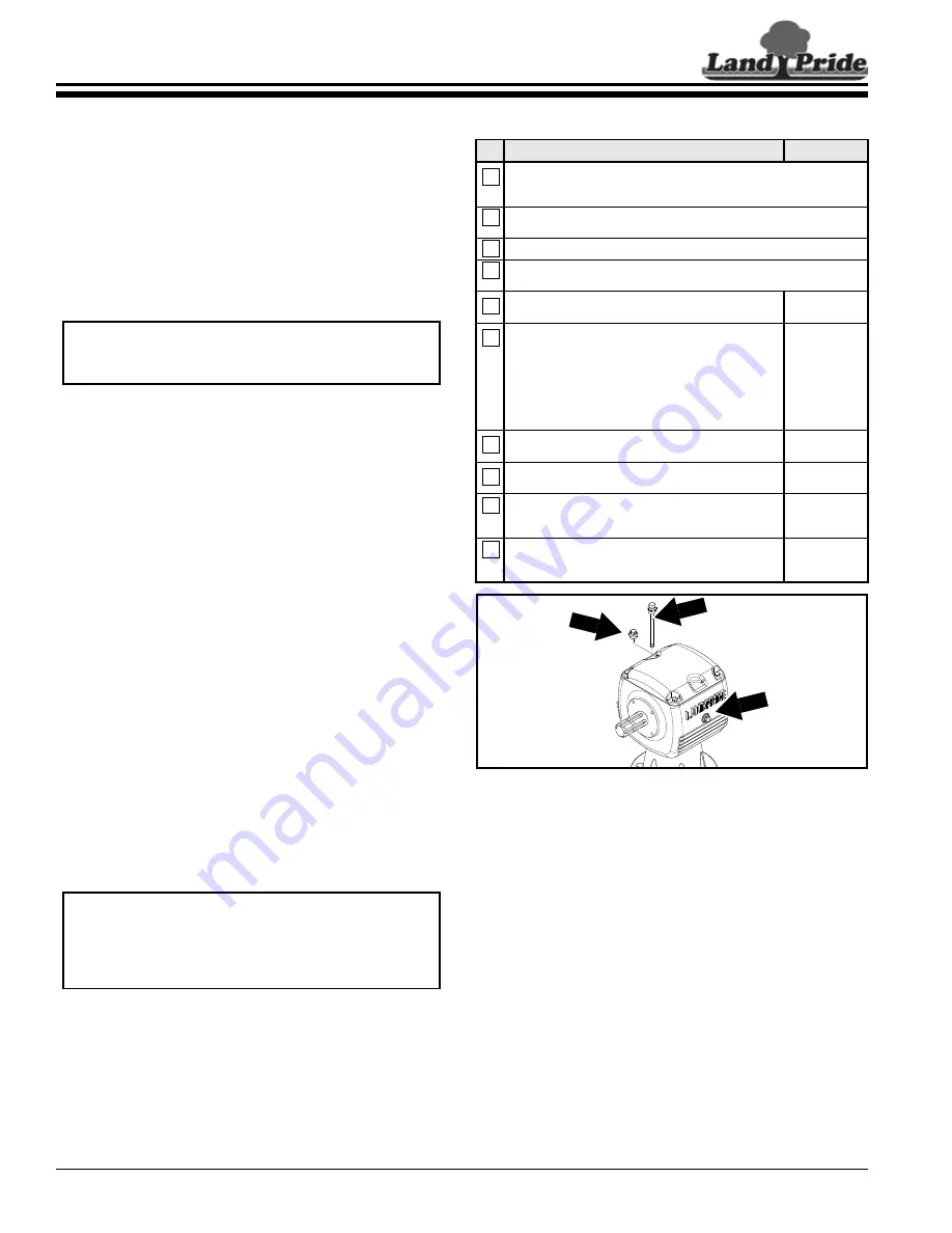
Vented Dipstick Installation

Refer to Figure 1-1:

A vented dipstick for the gearbox is included in a bag with 
the manual. See your nearest Land Pride dealer if 
dipstick is missing. Remove temporary red plug from top 
of splitter gearbox and replace with supplied dipstick.

NOTE:  

The tractor may need additional ballast to 

maintain steering control. See tractor’s Operator’s 
Manual to determine if additional ballast is required.

IMPORTANT: 

Gearboxes are shipped with solid 

plugs in them to prevent oil loss during shipping and 
handling. The solid plug on top of the gearbox must 
be replaced with a vented dipstick before operating 
the implement.

Installation of Vented Dipstick

Figure 1-1

Upper 3-Point Hitch Assembly

Refer to Figure 1-2 on page 11:

1.

Remove angle shipping brackets (not shown) with 
gauge wheel assemblies (#4) from mower frame.

2.

Remove rear hitch braces (#1), A-Frame hitch braces 
(#2), and clevis hitches (#3) from shipping crate.

3.

Attach rear hitch braces (#1) to hole “A1” inside of 
rear hitch mounting plates (#5) with 5/8" bolts and 
flanged lock nuts (#6) provided in rear hitch plates. 
Do not tighten nuts.

4.

Attach A-Frame hitch braces (#2) to holes “A2” inside 
front hitch mounting plates (#7) with 5/8" bolts (#8) 
and hex flanged lock nuts (#8) shipped holding rear 
hitch braces (#1) together. Do not tighten nuts.

5.

Remove 5/8" x 5 1/2" lg. bolt, lock washer, and 
nut (#11) from upper pivoting hitch (#9). Don’t let 
spacer tube (#10) fall from upper pivoting hitch.

Pre-Assembly Checklist

Check

Reference

Make sure miscellaneous assembly tools are on hand: Hammer, 
tape measure, hacksaw, assortment of wrenches & sockets, 
3/8" drill, drill bits and spirit level.

Have a forklift or hoist with properly sized chains and safety 
stands on hand capable of lifting 2500 lbs.

Have a minimum of two people available during assembly.

Check to see if auxiliary tractor weights are needed.
See Specifications on page 27 for mower weights.

Make sure all major components and loose parts 
are shipped with the implement.

Operator’s
Manual

Double check to make sure all fasteners & pins are 
installed in the correct location. Refer to the Parts 
Manual if unsure. 

NOTE:

 All assembled hardware from the factory 

has been installed in the correct location. 
Remember location of a part or fastener if 
removed. Keep parts separated.

Operator’s
Manual & 
Parts Manual

Make sure working parts move freely, bolts are 
tight & cotter pins are spread.

Operator’s
Manual

Make sure all grease fittings are in place and 
lubricated.

Section 5
Page 25

Make sure all safety labels are correctly located 
and legible. Replace if damaged.

Important 
Safety 
Information

Make sure all red reflectors are correctly located 
and visible when implement is in transport 
position.

Page 4

30216

DO NOT 

OVERFILL!


Oil Level 
Plug

Solid 

Plug

Vented Dipstick

Summary of Contents for PATRIOT FDR1648

Page 1: ...e see your Land Pride dealer Read the Operator s Manual entirely When you see this symbol the subsequent instructions and warnings are serious follow without exception Your life and the lives of other...

Page 2: ...achine weight and measurements provided in the Specifications Capacities Section of this manual with the Option s weight and measurements Dealer Contact Information Model Number Serial Number Machine...

Page 3: ...on 10 Upper 3 Point Hitch Assembly 10 Gauge Wheel Assembly 11 Lower 3 Point Clevis Hitch Assembly 11 Tractor 3 Point Hook up 12 Top Center Link Adjustment 12 Quick Hitch Hook up 13 Driveline Hook up t...

Page 4: ...priate App on your smart phone open the App point your phone on the QR code and take a picture Dealer QR Locator The QR code on the left will link you to available dealers for Land Pride products Refe...

Page 5: ...to play on the power machine or implement Use extra caution when backing up Before the tractor starts to move look down and behind to make sure the area is clear Safety at All Times Careful operation...

Page 6: ...laws Use towing vehicle and trailer of adequate size and capacity Secure equipment towed on a trailer with tie downs and chains Sudden braking can cause a towed trailer to swerve and upset Reduce spee...

Page 7: ...ating equipment Use Seat Belt and ROPS Land Pride recommends the use of a CAB or roll over protective structures ROPS and seat belt in almost all power machines Combination of a CAB or ROPS and seat b...

Page 8: ...Caution 818 540C Danger Guard Missing FDR1660 FDR1672 FDR1648 35784 20907 35785 13314 3 Some new equipment installed during repair requires safety labels to be affixed to the replaced component as sp...

Page 9: ...Table of Contents 10 26 17 5 FDR1660 FDR1672 FDR1648 35786 13314 35784 20905 ROTATING DRIVELINE KEEP AWAY 818 543C Danger Guard Missing 818 552C Danger Rotating Driveline 818 558C Warning General...

Page 10: ...Table of Contents 10 26 17 6 818 556C Danger Thrown Object 818 555C Danger Rotating Blade FDR1660 FDR1672 FDR1648 FDR1660 FDR1672 FDR1648 35785 20905 35787 20905...

Page 11: ...f Contents 10 26 17 7 FDR1660 FDR1672 FDR1648 FDR1648 1660 FDR1672 35786 20906 35784 838 270C Caution V Belt Installation FDR1648 FDR1660 FDR1672 818 142C Caution Rotating Drive Line FDR1648 FDR1660 F...

Page 12: ...ing forward in the direction the machine will operate while in use unless otherwise stated Definitions IMPORTANT A special point of information related to the following topic Land Pride s intention is...

Page 13: ...ction Table of Contents 10 26 17 9 FDR1660 FDR 1672 Serial Number Plate Location Figure 1A FDR1648 Serial Number Plate Location Figure 1B 35787 30278 Serial number plate located in one of two location...

Page 14: ...handling The solid plug on top of the gearbox must be replaced with a vented dipstick before operating the implement Installation of Vented Dipstick Figure 1 1 Upper 3 Point Hitch Assembly Refer to F...

Page 15: ...all remaining spacers 12 13 above each arm 4 Remove linchpins 21 from clevis hitch pin 1 Secure gauge wheels 4 to gauge wheel arms 14 with linchpins 21 Lower 3 Point Clevis Hitch Assembly Refer to Fig...

Page 16: ...from tractor 5 Insert lower hitch pins 1 through hitch clevis holes and lower lift arm holes Secure hitch pins with linchpins 5 NOTE Land Pride s Quick Hitch can be attached to the tractor to provide...

Page 17: ...ual in order to attach Quick Hitch to lower 3 Point arms and top link 39036 NOTE This will lock the lower 3 Point arms into position Use 3 Point tractor float instead Driveline Hook up to Gearbox Refe...

Page 18: ...if implement is hooked to different tractors or if a Quick Hitch is used IMPORTANT The driveline must be lubricated before putting it into service Refer to Lubrication Points on page 25 NOTE See Shor...

Page 19: ...ure and record Maximum Allowable Length as shown in Figure 1 7 Record Maximum Allowable Length here ________ 4 Reattach inner driveline yoke to gearbox shaft and outer driveline yoke to tractor s PTO...

Page 20: ...e s medium lift blades are great when horsepower is a concern They produce a medium suction to lift grass and require less horsepower than high lift blades High Lift Blades Land Pride s high lift blad...

Page 21: ...if vibration occurs 8 Investigate the cause of vibration Make necessary corrections before continuing Section 3 Operating Instructions Operating Check Hazard control and accident prevention are depen...

Page 22: ...s dirt mounds tree stumps posts large rocks holes and drop offs with a visible flag Do not use mower blades for a fan Mower blades are not properly designed or guarded for this use Using mower blades...

Page 23: ...iveline It will also defeat the purpose of the tractor s power take off shield Select a safe ground speed when transporting Never travel at a speed which does not allow adequate control of steering an...

Page 24: ...les such as trees buildings or fences When you have arrived at the mowing site start the tractor raise the deck to make sure that everything is properly attached and that the driveline is not in a bin...

Page 25: ...uge wheel spindle 3 Position full length spacers and half spacer as required All spacers on top of spindle tube allows for approximately 3 4 cutting height Adjustments range from 3 4 to a maximum of 5...

Page 26: ...ition and installed before power take off is engaged Never allow fingers hands or other body extremities to come near a moving V belt or pulley Doing so can result in server bodily injury or death Per...

Page 27: ...ncing Figure 5 3 IMPORTANT Replace mower blades in pairs with genuine Land Pride blades only Not replacing both blades will result in an out of balance condition NOTE Care should be taken in order not...

Page 28: ...il may also be applied to the lower deck area to minimize oxidation 2 Check blades and blade bolts for wear and replace if necessary See Service Mowing Blades on page 22 3 Inspect mower for loose dama...

Page 29: ...s Inner Tube Bearings Type of Lubrication Multi purpose Grease Quantity As Required Driveline Profiles Type of Lubrication Multi purpose Grease Quantity Clean coat inner profile tube of driveline with...

Page 30: ...e of Lubrication 80 90W EP Gear Lube Quantity Fill until oil reaches top mark on dipstick or begins to flow out side plug hole in gearbox IMPORTANT Do not overfill gearbox with oil Oil will expand whe...

Page 31: ...FPM 18 130 FPM Blade Construction 3 ea 1 4 x 2 1 2 x 16 7 8 Heat Treated Alloy Steel 1 4 x 2 1 2 x 21 Heat Treated Alloy Steel 1 4 x 2 1 2 x 25 Heat Treated Alloy Steel Blade Options Standard Blades...

Page 32: ...Heavy duty Gauge wheel arms 1 4 Gauge wheel arms increases strength Non aligned gauge wheels Rear wheels don t track behind the front wheels to reduce laying grass over High Blade Tip Speed 48 16 203...

Page 33: ...lt guard shields and clean sheaves Tighten spring take up eyebolt Replace belt Patches of uncut grass Mow at full throttle 540 PTO rpm check PTO speed and tractor engine Shift transmission to a lower...

Page 34: ...16 X 1 5 155 115 240 180 335 245 5 8 18 150 110 230 170 325 240 M18 X 2 5 195 145 310 230 405 300 3 4 10 235 170 360 265 510 375 M18 X 1 5 220 165 350 260 485 355 3 4 16 260 190 405 295 570 420 M20 X...

Page 35: ...designed Misuse also specifically includes failure to properly maintain oil levels grease points and driveline shafts Claims under this Warranty must be made to the dealer which originally sold the p...

Page 36: ...Corporate Office P O Box 5060 Salina Kansas 67402 5060 USA www landpride com...

Reviews: