Section 1: Assembly & Set-up
PD10, PD15, PD25 & PD35 Post Hole Diggers 317-048M
8/9/19
14
Frame Assembly
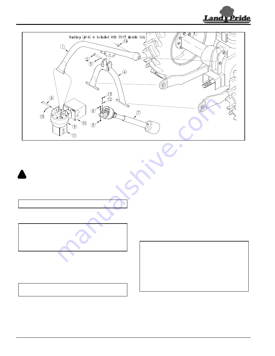
Refer to Figure 1-1:
DANGER
!
To avoid serious injury or death:
1.
Remove the tractor top center 3-point link. Keep hitch
pin and retaining pin for future use.
2.
Attach boom (#1) to the tractor’s top center link hole
using existing hitch pin and retaining pin.
3.
Attach digger yoke (#4) to the tractor’s lower 3-point
lift arms with two 5/16" x 1 3/4" linchpins. (Linchpins
supplied by customer.)
4.
Connect sway bars or adjust sway links to retain
digger side to side movement.
5.
Rotate boom (#1) and yoke (#4) up until pin (#2) can
be inserted into the middle hole under the boom.
6.
Insert pivot pin (#2) and secure with cotter pin (#3).
Bend one or more legs of cotter pin to retain pin.
NOTE:
Assembly is easier with the use of a tractor.
NOTE:
PD15 Only: A 3/4" bushing (#14) is included
with all PD15 Post Hole Diggers. Use this bushing
when connecting digger boom (#1) to the tractor’s
top center link point with 3/4" hitch pin. Bushing is
omitted in hook-up when using a 1" hitch pin.
NOTE:
For narrow 3-point tractors, use the yoke’s
inner pins when connecting to PD10 & PD15 diggers.
7.
The boom and yoke pivot connection may need
readjusting to best suit your tractor configuration to
get desired hole depth and auger transport
clearance. Refer to
8.
The gearbox and guard assemblies consists of items
(#9, #10, & #11) which have been factory assembled.
9.
Raise the tractor’s lower 3-point arms until the end of
boom is approximately 18" above ground.
10. Remove one cotter pin (#15) from hanger pin (#6)
and then remove hanger pin.
11. Align gearbox mounting holes with boom mounting
hole and reinsert hanger pin (#6). Secure hanger pin
with cotter pin (#15). Bend one or more legs of cotter
pin to keep it from falling out.
12. The gearbox is shipped without gear lube. Refer to
on page 37 for detailed
instructions.
IMPORTANT:
Cab tractors: Glass can break if
NOTE:
It may be necessary to move center 3-point
hitch pin to the top mounting hole on the tractor
and/or adjust yoke and yoke pin to a mounting hole
farther away from the tractor. Refer to
PD15 Series Frame Assembly
Figure 1-1
14770


