Section 4: Options and Accessories
PD10, PD15, PD25 & PD35 Post Hole Diggers 317-048M
8/9/19
31
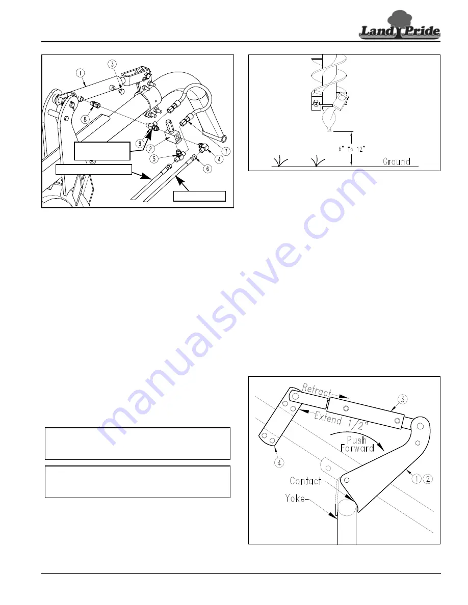
Down Pressure Cylinder Plumbing
Figure 4-17
Refer to Figure 4-17:
14. Install hydraulic plumbing using teflon tape to seal
pipe threads. Do not tighten connections until after all
fittings have been installed.
a. Connect plug (#3) to rod end of hydraulic cylinder.
b. Connect straight fitting (#8) to clevis end of
hydraulic cylinder.
c. Connect shuttle tee fitting (#9) to straight fitting.
d. Connect pressure relief valve (#2) to shuttle tee.
e. Connect standard tee fitting (#5) to the bottom end
of pressure relief valve.
f. Connect 90
o
elbow fitting (#4) to remaining port of
pressure relief valve.
g. Connect 3/8" x 15 3/4" bypass line (#7) to shuttle
tee (#9) and standard tee (#5).
h. Connect 3/8" x 84 1/2" pressure line (#6) to
90
o
elbow fitting (#4).
i. Connect pressure line (#6) to the tractor hydraulic
outlet.
j. Connect customer supplied Return line to tee
fitting (#5).
k. Connect customer supplied return line to reservoir
or sump.
26829
Return Line to Sump
Pressure Line
Shuttle Tee
Nut Placement
IMPORTANT:
Do not connect return line to the
NOTE:
Customer to provide return line to sump and
fittings to connect return line to tee fitting (#5) and to
the tractor sump.
Setting Down Pressure Kit
Figure 4-18
Adjust Down Pressure Kit
Refer to Figure 4-18:
1.
Raise Post Hole Digger so that auger tip is 6" to 12"
above ground.
2.
Set tractor 3-point up-stop to limit auger maximum
raised height to 12". Exceeding this height can cause
undue stress on Driveline and cause driveline
damage.
Refer to Figure 4-19:
3.
Loosen bolts in clamp plates (#4).
4.
Push top of cylinder mounting plates (#1 & # 2)
forward toward the tractor until plates have firmly
contacted digger yoke.
5.
Make sure cylinder clamp plates (#4) will move fairly
free on digger boom and that cylinder (#3) is fully
retracted.
6.
Extend cylinder (#3) 1/2" and tighten bolts in clamp
plates (#4) evenly to 76 ft-lbs.
Set Down Pressure Kit
Figure 4-19
14837
14838


