Section 1: Assembly & Set-up
RC5610, RC6610, RCM5610, & RCM6610 Series 2 S/N Rotary Cutters 330-539M
5/6/20
24
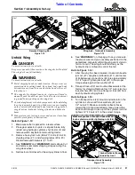
Hydraulic Lift Cylinder With Stroke Control Spacers
Figure 1-19
Driveline Hanger Adjustment
Refer to Figure 1-19:
1. Move tractor control lever to extend hydraulic lift
cylinder (#1) until pressure against stroke control
spacers (#4) is removed.
2. Shut tractor down properly before dismounting. Refer
3. Remove all stroke control spacers (#4) from center
hydraulic lift cylinder (#1) by spreading them apart at
the break line.
4. Start tractor and lower cutter until front skids are
resting on the ground or on support blocks.
5. Shut tractor down properly before dismounting.
6. Replace stroke control spacers (#4) as needed to
support wheels at this position.
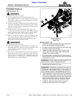
Refer to Figure 1-20:
7. With driveline attached to tractor, rotate driveline
hanger (#1) up as shown.
8. Loosen nuts securing carriage bolts (#4) and adjust
driveline hanger (#1) up until there is a small gap
between driveline (#5) and hanger (#1).
9. If driveline hanger (#1) is adjusted fully up and needs
to adjust higher, remove carriage bolts (#4) and
reattach hanger to the upper two square holes (#2)
with existing flat washers, lock washers, hex nuts,
and carriage bolts (#4). Continue to adjust hanger to
underside of driveline.
10. Draw nuts securing carriage bolts (#4) up snug and
rotate driveline hanger (#1) down. If hanger makes
contact with driveline (#5), readjust hanger down
until it misses the driveline.
11. Tighten 3/8"-16 GR5 bolts (#3) to the correct torque.
12. Rotate driveline hanger (#1) down.
37840
IMPORTANT:
Always rotate driveline hanger down
after hook-up to prevent driveline damage.
Driveline Hanger Adjustment
Figure 1-20
Driveline Clearance Check
Check driveline for adequate clearance under all ranges
of cutter height.
1. With driveline shaft attached to the tractor, slowly
raise and lower cutter to its upper and lower limits
while observing clearances between hitch and
driveline. Adjust tractor drawbar height and/or length
if driveline interferes. See Figure 1-1 on page 14 for
correct drawbar dimensions.
2. It may be necessary to purge lift cylinder, wing
cylinder, and hydraulic hoses of trapped air if
operation is sluggish. Cycle cylinders back and forth
several times to purge air from them. For additional
details, see
37657


