Section 1: Assembly & Set-up
RC5610, RC6610, RCM5610, & RCM6610 Series 2 S/N Rotary Cutters 330-539M
5/6/20
21
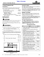
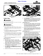
Remove Shipping Bar
Figure 1-13
Unfold Wing
DANGER
!
To avoid serious injury or death:
Keep everyone out of the area where the wing deck will unfold.
The wing deck can fall suddenly.
WARNING
!
To avoid serious injury or death:
•
Metal shipping bands are under tension. Always wear eye
protection when cutting bands. Keep head, body, and body
extremities away from the area where the band will recoil
•
The wing deck is shipped leaning in. A person will need to
manually push the deck out pass vertical to start its descent
to ground before pushing on the wing deck.
•
Avoid entanglement with deck components while unfolding
the wing in assembly and sit-up. Make sure you are standing
on the center deck behind and away from the wing gearbox,
wing driveline, hydraulic folding cylinder, and hydraulic
•
Make certain your footing is secure and you are clear of any
possible pinch points or obstructions.
Refer to Figure 1-13:
1. Make sure cutter is parked on a level surface.
2. Place gear selector in park or set park brake, fully
retract wing hydraulic cylinder, shut tractor off, and
remove switch key before dismounting tractor.
3. Remove hex nylock nuts (#6 & #7), bolts (#4 & #5),
shipping strap (#1), and shipping tubes (#2 & #3).
Discard removed hardware (#1 to #7).
4. See “
DANGER
” and “
WARNINGS
” alerts above. Cut
and remove rear metal shipping strap securing the
wing deck wheel.
5. Set tractor control lever for the wing cylinder in float.
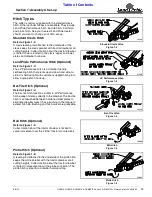
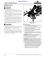
37647
Wing Axle - Turnbuckle Assembly
Figure 1-14
6. See “
WARNINGS
”
on this page. Once you are sure
the area is clear and you are safely positioned on the
center deck, manually unfold the wing until it starts to
fall on its own. The wing should fall slowly as the
hydraulic line is orificed to control the fall.
Refer to Figure 1-14:
7.
After the wing has been lowered, loosen turnbuckle
jam nut (#7). Lengthen turnbuckle (#11) until center
of bolted swivel connections (#5) are approximately
10 1/2" apart. Tighten jamb nut (#7) to the proper
torque value against lock washer (#10).
8. Transport locks (#2) are mounted backwards at the
factory for shipping. Remove four 1/2" nuts (#6), four
lock washers (#9), and one transport lock (#2) from
each hydraulic wing cylinder.
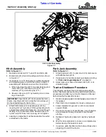
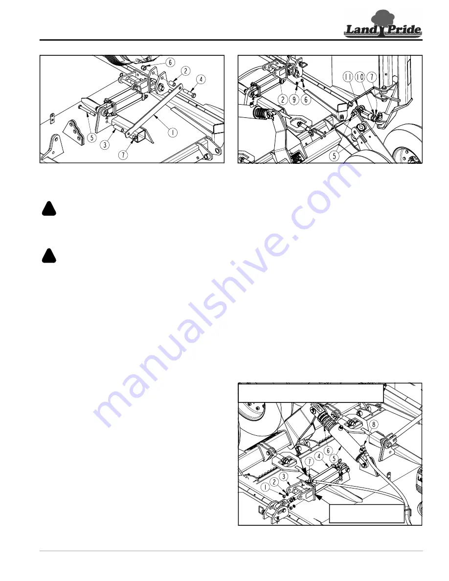
Refer to Figure 1-15:
9. Turn transport lock (#3) around and reinstall on the
cylinder as shown with lock washers (#2) and
1/2" nuts (#1). Make sure amber reflector faces
toward the front and red reflector faces toward the
back. Hold transport lock up off the cylinder rod and
tighten 1/2"-13 nuts (#1) to the correct torque.
Transport Lock Assembly
Figure 1-15
26714
Amber Reflector Faces
toward the front
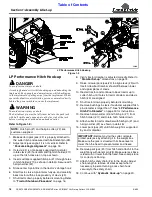
Make sure groove in transport lock does not
touch cylinder rod after tightening nuts (#6).
37841


