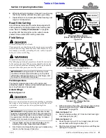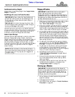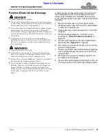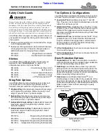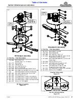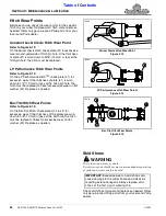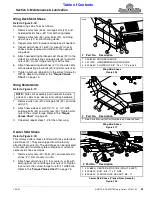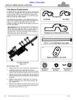
Section 5: Maintenance & Lubrication
RC5715 & RCM5715 Rotary Cutters 331-431M
1/20/21
55
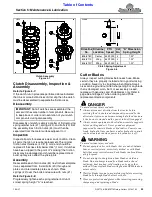
Clutch Assembly
Figure 5-7
Clutch Disassembly, Inspection &
Assembly
Refer to Figure 5-7:
If the clutch run-in procedure performed above indicated
that one or more friction disks did not slip, then the clutch
must be disassembled to separate the friction disks.
Disassembly
Disassembly of clutch is simply a matter of first removing
spring retainer nuts (#1), springs (#2), and bolts (#3) from
the assembly. Each friction disk (#4) must then be
separated from the metal surface adjacent to it.
Inspection
Inspect all parts for excessive wear and condition. Clean
all parts that do not require replacement.The original
friction disk thickness is 1/8" (3 mm) and should be
replaced if thickness falls below 3/64" (1 mm). If clutches
have been slipped to the point of “smoking”, the friction
disks may be damaged and should be replaced. Heat
build-up may also affect the yoke joints.
Assembly
Reassemble each friction disk (#4) next to the metal plate
it was separated from. Install bolts (#3) through end
plates and intermediate plates as shown. Place
springs (#2) over the bolts and secure with nuts (#1).
Refer to Figure 5-8:
Progressively tighten each spring retainer bolt until
correct spring height “A” is reached.
23554
IMPORTANT:
Not all clutches are assembled the
same with the same number of components. Be sure
to keep track of order and orientation of your clutch
components during disassembly.
g
Clutch Spring Adjustment
Figure 5-8
Cutter Blades
Always inspect cutting blades before each use. Make
certain they are properly installed and in good working
condition. Never try to straighten a bent blade. Small
nicks can be ground out when sharpening. For any blade
that is damaged, worn, bent, or excessively nicked,
replace with genuine Land Pride blades only. Refer to
when ordering Land Pride
replacement blade components.
DANGER
!
To avoid serious injury or death:
•
Always disconnect driveline from the tractor before
servicing the drivetrain and components powered by the
drivetrain. A person can become entangled in the drivetrain
if the tractor is started and the power take-off is engaged.
•
Always secure equipment with solid, non-concrete supports
before working under it. Never go under equipment
supported by concrete blocks or hydraulics. Concrete can
break, hydraulic lines can burst, and/or hydraulic controls
can be actuated even when power to hydraulics is off.
WARNING
!
To avoid serious injury or death:
•
Do not operate cutter with blades that are out-of-balance,
bent, excessively worn, excessively nicked, or with blade
bolts that are excessively worn. Such blades can break loose
•
Do not attempt to straighten a bent blade or weld on a
blade. Do not attempt to modify a blade such as hard
surfacing, heat treating, cold treating, or by any other
method. Always replace blades with genuine OEM blades to
•
Wait for blades to come to a complete stop before accessing
blade bolts through blade bolt access hole.
•
Wear eye protection and gloves while inspecting, removing,
sharpening, and replacing a blade.
Driveline
No.
Driveline
Location
PTO
Speed
Cat
No.
“A” Dimension
Spring Height
826-818C
Center
540/1000
4
1.32"
826-811C
Wing
540/1000
4
1.32"
826-812C
Wing
540/1000
5
1.32"
24600

