Section 1: Assembly & Set-up
RC5715 & RCM5715 Rotary Cutters 331-431M
1/20/21
23
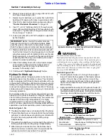
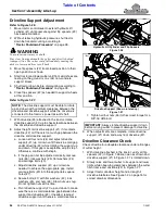
6. Raise or lower park jack (#3) to align hitch (#10) with
bolt hole in swivel clevis (#9).
7.
Restart tractor and back up to cutter hitch until hitch
bushing (#10) aligns with holes in swivel clevis (#9).
8. Shut tractor down before dismounting according to
9. Insert 1" x 6 1/2" GR5 hex bolt (#2) through swivel
clevis (#9) and hitch bushing (#10). Secure bolt with
locknut (#1). Tighten locknut snug to remove all play.
Do not torque 1" locknut.
10. Lower park jack (#3) until hitch weight is supported
by the drawbar.
11. Remove detent pin (#8) and relocate park jack (#3)
from the hitch mount to the storage mount on the left
wing. Secure jack with its detent pin. Ensure the jack
base is level with, or lower than the jack crank head,
especially after the wings are folded up. See cover
picture for correct positioning.
12. Attach hitch safety chain (#4) to the tractor. Adjust
chain length to remove all slack except what is
necessary to permit turning. Lock chain hook
securely to the safety chain.
Hydraulic Hook-up
The required number of duplex outlets on the tractor is
dependent upon how the cutter is set-up. The standard
cutter is equipped with three hydraulic cylinders with one
in the center for lifting the cutter and one on each wing for
folding the wings simultaneously. The center lift cylinder
is set up for single-action (one way) operation. The wings
can be set up with single-action (one-way) or dual-action
(two-way) operation.
Each duplex outlet on your tractor can perform just one
operation. One outlet is needed for lifting the cutter and
one for folding the wings simultaneously. Two outlets are
needed to fold the wings independently. It is highly
recommended to connect the wing fold hose (single-
action) or hoses (dual-action) to a duplex outlet with float
capabilities. Use float capabilities when in field operation.
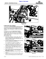
Refer to Figure 1-16:
•
The black handled hose is connected to the lift cylinder.
•
The red handled hose is connected to both wing folding
cylinders for simultaneous wing folding or connected to
the right hand wing cylinder when folding wings
independently.
•
The yellow handled hose is connected to the left wing
folding cylinder when folding wings independently.
•
When setup for dual-action fold, the handles have
directional arrows to identify which hose extends the
cylinder and which hose retracts the cylinder.
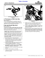
IMPORTANT:
Before moving the cutter, relocate
park jack by storing it on the left wing deck. Make
sure the jack is stored with its base level or lower
than the head to prevent water and freeze damage.
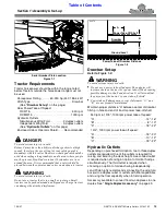
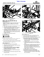
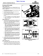
Hydraulic Hook-up (Constant Level Clevis Hitch Shown)
Figure 1-15
WARNING
!
To avoid serious injury or death:
Hydraulic fluid under high pressure can penetrate the skin
and/or eyes causing a serious injury. Wear protective gloves
and safety glasses or goggles when working with hydraulic
systems. Use a piece of cardboard or wood rather than hands
when searching for leaks. A doctor familiar with this type of
injury must treat the injury within a few hours or gangrene
Refer to Figure 1-15:
1. Route hydraulic hoses (#1) through hose support
loop (#2) and attach couplers to the tractor remote
outlets. If tractor has a float option on one of the
outlets, connect wing lift hose to that outlet and set
tractor control lever for that outlet in float position
before cutting.
2. Apply spiraled hose wrap (#3) to hydraulic hoses (#1)
as needed to keep hoses from becoming pinch while
raising and lowering the decks, folding and unfolding
the wings, and while making turns with the tractor.
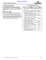
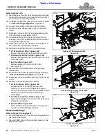
Hydraulic Hose Hand Grips
Figure 1-16
72220
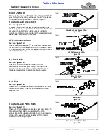
Hand Grips with Cylinder Extension Symbol
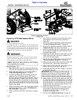
Hand Grips with Cylinder Retraction Symbol
Handle Color
Operation
Black Handle:
Engages lift cylinder to raise
Red Handle:
Simultaneous fold/Right wing fold
Yellow Handle:
Left wing fold
35553


