Section 1: Assembly & Set-up
RC5715 & RCM5715 Rotary Cutters 331-431M
1/20/21
31
Unhook Rotary Cutter
DANGER
!
To avoid serious injury or death:
Do not walk, stand, or allow anyone else in the area where a
raised wing will fall unless the wing is securely locked in the
raised position with its transport lock.
WARNING
!
To avoid serious injury or death:
Stay clear from underneath the cutter and directly behind
transport tires. The cutter could fall suddenly causing the
decks to lower and tires to roll back.
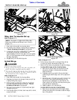
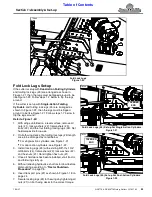
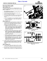
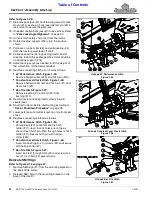
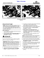
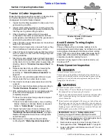
Refer to Figure 1-32:
on page 62 when storing
the cutter for long periods and at end of the season.
2. If power take-off is engaged, reduce tractor engine
speed to an idle and then disengage power take-off.
3. Park cutter on a level, hard surface. Place tractor gear
selector in park or set park brake.
4. Wait for the blades to come to a complete stop, and
then raise the cutter up until all pressure is removed
from flip spacers (#2).
5. With the blades stopped, fold the wings fully up.
6. Without relieving hydraulic pressure to the lift cylinder
and wing fold cylinders, shut tractor off according to
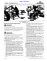
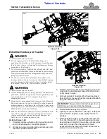
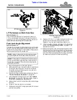
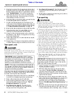
Refer to Figure 1-33:
7.
Remove hairpin cotters (#1) and transport pins (#2)
from storage holes (#4).
8. Insert transport pins (#2) through transport lock
holes (#3) and secure them with hairpin cotters (#1).
Refer to Figure 1-32:
9. Move all flip spacers (#2) to the open position.
10. Start tractor and lower the cutter fully down. The front
skid shoes should be resting on the ground or on
solid, non-concrete support blocks.
11. Without relieving hydraulics, shut tractor down before
dismounting according to
12. Close stroke control flip spacers as needed to
support wheels at this position.
13. Move tractor hydraulic control levers back and forth to
release all hydraulic pressures at the couplers.
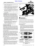
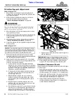
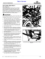
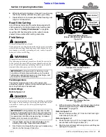
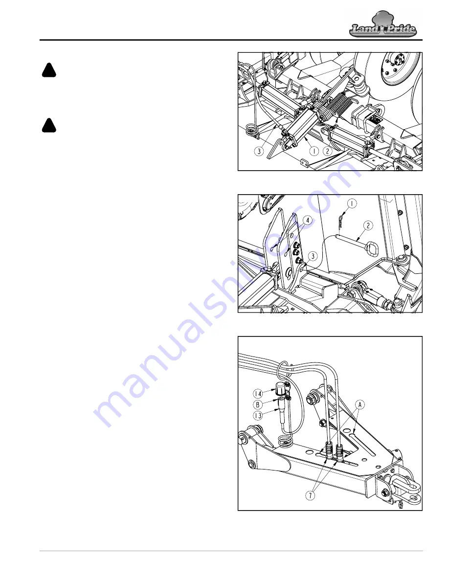
Refer to Figure 1-34:
14. Unhook hydraulic hoses from the tractor outlets.
Insert couplers (#7) through hole (A) on one side of
the hitch and slide couplers down the slot to secure
them and to keep them out of the dirt.
15. Unhook wire harness (#13) from the tractor outlet.
16. Align boss (B) with notch in holder (#14). Insert
connector (#13) into the holder and then turn it one-
quarter of a turn to secure it and keep moisture out.
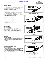
Hydraulic Lift Cylinder and Flip Spacers
Figure 1-32
Transport Pin, Locked Position
Figure 1-33
Hydraulic Couplers & Wire Harness Storage
Figure 1-34
72238
73870
73865
70487

