Section 2: Adjustments
RC5715 & RCM5715 Rotary Cutters 331-431M
1/20/21
33
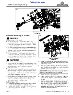
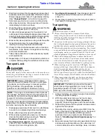
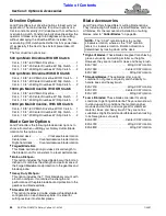
LP Performance Hitch Hole Size
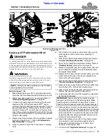
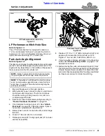
Figure 2-1
LP Performance Hitch Hole Size
Refer to Figure 2-1:
The LP Performance Hitch is designed to receive a
1" (2.5 cm) diameter hitch pin. To convert the hitch to
receive a 1 1/4" (3.2 cm) diameter hitch pin, knock out
upper and lower bushings (#1) in clevis (#2).
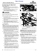
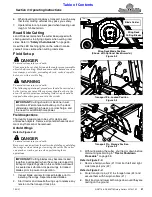
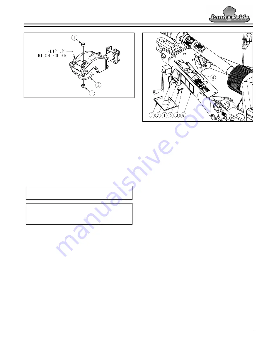
Park Jack Angle Alignment
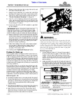
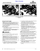
Refer to Figure 2-2:
The jack mount angle should be adjusted to position park
jack (#7) vertical while supporting the cutter hitch. This
angle will vary depending on the number of flip spacers
that are closed on the lift cylinder rod.
1. Move all flip spacers to the open position.
2. With hydraulic hoses hooked to a tractor, start tractor
and lower cutter fully down. The front skid shoes
should be resting on the ground or on solid, non-
concrete support blocks.
3. Shut tractor down before dismounting according to
4. If not installed, install park jack (#7). See
on page 18. Check jack angle. If jack is
not vertical, proceed with step 5 below.
5. Remove hex nut (#3), lock washer (#5) and carriage
bolt (#2).
6. Loosen 1" hex nut (#4). Do not remove.
7.
Rotate jack mount (#1) to align park jack (#7) as near
vertical as possible.
39093
NOTE:
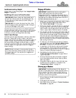
Refer to decal (#6) and instructions below
for jack alignment and torque value instructions.
NOTE:
If the cutter is not hitched to a tractor, place
solid, non-concrete support blocks under the front
skid shoes to support the cutter while aligning the
park jack vertically.
Park Jack Angle Alignment
Figure 2-2
8. Replace 1/2"-13 x 1 1/2" GR5 carriage bolt (#2) and
secure with lock washer (#5) and hex nut (#3).
Tighten 1" hex nut (#4) to 645 ft-lbs (874.4
N· m
).
9. If moving cutter, continue with step 10. If unhooking
cutter, see
on page 31 for
detailed instructions.
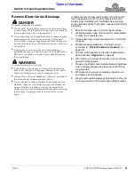
10. Before moving the cutter, relocate park jack (#7) from
the hitch mount to the storage mount on the left wing.
Ensure the jack base is level with or lower than the
jack crank head, especially after the wings are folded
up. See cover picture for correct positioning.
73910
Section 2: Adjustments


