Section 5: Maintenance & Lubrication
7/13/20
RCD1884 Rotary Cutters 326-355M
28
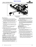
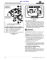
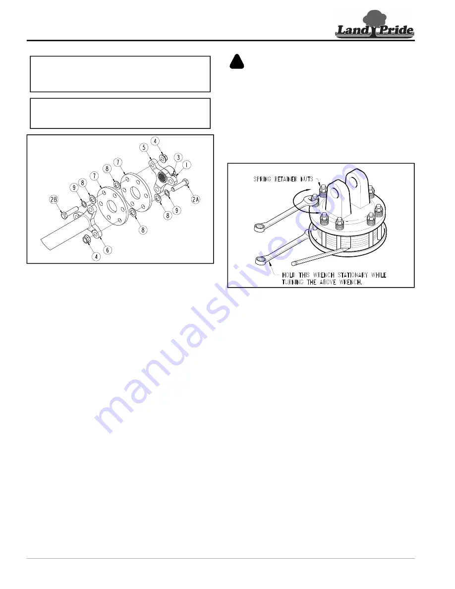
Flex Coupler Assembly
Figure 5-3
1. Unbolt/remove rubber discs (#7) from flex coupler.
Keep rubber discs that are in good shape and
replace them if they are wrinkled excessively.
2. Loosen jam nut (#3) and set screw (#1).
Slide spider (#5) off main gearbox output shaft.
3. Rotate cutter blades until blades on the left dishpan
are 90
o
to blades on the right dishpan.
4. Hold blades 90
o
apart. Center spider lugs (#5)
between spider tube lugs (#6) and push spider (#5)
onto main gearbox output shaft.
5. Attach rubber discs (#7) to spider tube lugs (#6) with
existing bolts (#2A), washers (#9), bushing (#8), and
hex flange locknuts (#4) as shown. Do not tighten.
6. Attach rubber discs (#7) to spider lugs (#5) with
existing bolts (#2B), washers (#9), bushing (#8), and
hex flange locknuts (#4) as shown. Do not tighten.
7. Tighten nuts (#4) evenly until rubber disc (#7) touch
each other at each bolt location. Bushings (#8)
should be compressed halfway into the rubber discs.
Driveline Protection
The drive-train is protected from shock loads with a four
plate slip-clutch. The slip-clutch must be capable of
slippage during operation. Always do a “clutch run-in”
operation at the beginning of each season and after long
periods of inactivity to remove any oxidation that may
have accumulated on the friction surfaces. Repeat
“clutch run-in” instructions when moisture and/or
condensation seizes the inner friction plates.
IMPORTANT:
See Figure 5-2. Cutter blades must be
90 deg. to each other to be in time or blades will
contact each other when hitting solid objects such as
IMPORTANT:
Through use or hitting solid objects,
rubber discs can become worn causing blades to be
out of time. Replace worn rubber Discs.
33025
WARNING
!
To avoid serious injury or death:
Always place tractor in park or set park brake, disengage
power take-off, shut tractor engine off, remove ignition key,
and wait for all moving parts to stop before dismounting
Clutch Run-In
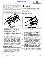
Refer to Refer to Figure 5-4:
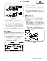
1. Using a pencil or other marker, scribe a line across the
exposed edges of the clutch plates and friction discs.
Clutch
Figure 5-4
2. Carefully loosen each of the 8 spring retainer nuts by
exactly 2 revolutions. It will be necessary to hold hex
end of retainer bolt in order to count the exact
number of revolutions.
3. Start tractor and engage power take-off drive for 2-3
seconds to permit slippage of the clutch surfaces.
Disengage power take-off, then re-engage a second
time for 2-3 seconds. Disengage power take-off, shut
off tractor, and remove key. Wait for all components to
stop before dismounting from tractor.
4. Inspect clutch and ensure that the scribed markings
made on the clutch plates have changed position.
Slippage has not occurred if any two marks on the
friction disc and plate are still aligned. A clutch that
has not slipped must be disassembled to separate
5. Tighten each of the 8 spring retainer nuts on the
clutch housing exactly 2 revolutions to restore the
clutch to the original setting pressure.
6. The clutch should be checked during the first hour of
cutting and periodically each week. An additional set
of scribe marks can be added to check for slippage.
13693

