Section 1: Assembly & Set-Up
RCFM4014 Rotary Cutter 326-730M
12/11/18
13
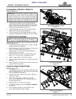
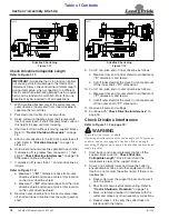
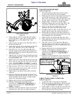
Intermediate Driveline Rotation
1.
Intermediate drivelines rotate counterclockwise
when viewing the T-box from the left side as shown.
Always verify intermediate drivelines are installed
correctly during assembly and set-up.
2. Switch drivelines if arrows (#1) on both drivelines
indicate the clutches rotate clockwise.
3. If only one arrow (#1) indicates the clutch rotates
clockwise, replace that driveline with a new driveline.
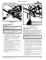
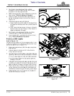
3-Point Hitch Assembly
1.
Cut bands securing A-frame hitch (#1 & #2) and rear
floating top link (#3) together.
2. Attach floating top link (#3) to A-frames (#1 & #2) with
3/4"-10 x 4" GR5 cap screw (#4), flat
washers (#6), 1" OD x 3 3/32" long bushing (#7),
and locknut (#5) as shown.
3. Attach driveline hook (#10) to A-frame (#1) using
5/16"-18 x 1 1/4" bolt (#11) and locknut (#12).
4. Tighten locknut (#5) to the correct torque.
5. Remove shipping bolts and nuts (not shown) in hitch
pins (#8).
6. Insert hitch pins (#8) into clevis holes as shown and
secure with linchpins (#9).
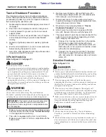
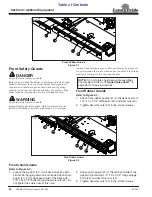
Gearbox Input Shaft Shield
1.
If installing driveline, remove shaft protector (#4) from
input shaft of gearbox (#7). Do not remove if driveline
will be installed at a later date.
2. Unsnap one end of shield access doors (#6) and
rotate doors open.
3. Attach shaft shield (#5) to gearbox (#7) with
W10-1.5 x 20 GR8.8 bolts (#1), lock washers (#3),
and flat washers (#2).
4. Tighten bolts (#1) to the correct torque.
5. If installing driveline, skip to
6. If not installing driveline, rotate shield access
doors (#6) closed and snap in place.
IMPORTANT:
The spring loaded flex couplers (#2)
are directional rotation and must be attached to the
T-box with arrows (#1) on end of clutches pointing in
the direction the intermediate drivelines will rotate. If
installed with indicator arrow rotating backwards, the
drivelines and/or gearboxes can become damaged.
NOTE:
Do not tighten hardware until assembly is
complete. See
“Torque Values Chart”
Intermediate Driveline Rotation
Figure 1-3
3-Point Hitch Assembly
Figure 1-4
T-Box Input Shaft Shield
Figure 1-5
37214
37156
37246


