Section 1: Assembly & Set-Up
RCFM4014 Rotary Cutter 326-730M
8/11/14
14
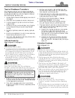
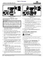
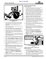
Installation of Center Tailwheel
Figure 1-7
Center Tailwheel Assembly
Depending on which option was purchased, the cutter
will be set-up with two or three tailwheels. If there are
three tailwheels, the third tailwheel is installed in the
middle of toolbar (#4). If only two tailwheels are provided,
skip to
“End Tailwheels for 38" & 40" Rows”
1.
Attach trailing arm (#3) to rear tool bar (#4) with
4" tube clamp (#7), 5/8"-11 x 2" GR5 bolts (#8), flat
washers (#12), and hex locknuts (#10). Make sure
trailing arm is centered on the rear tool bar and draw
all six nuts up snug. Do not tighten nuts until step #2.
2. Tighten the center two hex locknuts (#10) and then
the four corner locknuts (#10) in a crisscross pattern.
3. Repeat step 2 making sure all six nuts are tightened
to the correct torque.
4. Install large washer (#5) over tailwheel spindle (#1).
5. Insert tailwheel spindle (#1) into trailing arm (#3).
Push tailwheel up until adjusting collar (#2) is against
the trailing arm (#3).
6. Lower top collar (#6) over tailwheel spindle (#1) until
against trailing arm (#3).
7.
Secure top collar (#6) with 3/8"-16 x 3 1/4" GR8
bolt (#9) and nylock nut (#11). Tighten nylock nut to
the correct torque.
37160
IMPORTANT:
below must be followed when
tightening Lock nuts (#10).
IMPORTANT:
Discard hardware mounting tailwheel
to shipping crate. Use bolts, flat washers, and
locknuts in bolt bag to mount tailwheel to cutter axle.
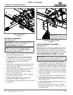
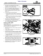
Driveline Installation
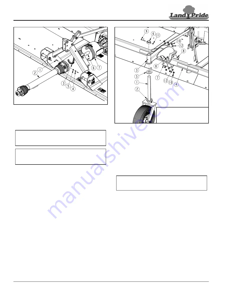
Figure 1-6
Driveline Installation
1.
If not already done, remove shaft protector (#6) from
gearbox input shaft and discard.
2. If not already done, unsnap one end of gearbox
shield access doors (#7) and rotate doors open.
3. Remove existing nut (#4), flat washer (#5), and
conical dog pin (#1) from slip-clutch end of
driveline (#2).
4. Slide u-joint on slip-clutch end of driveline (#2) onto
gearbox input shaft. Make certain the slip-clutch is
fully onto the shaft splines.
5. Attach slip-clutch end of driveline to gearbox input
shaft with removed conical dog pin (#1), flat
washer (#5), and nut (#4). Tighten conical dog
pin (#1) to 45-50 ft-lb torque.
6. Push/pull on driveline yoke to ensure it is securely
fastened to the gearbox shaft.
7.
Rotate driveline support (#3) down and place
driveline (#2) in driveline support (#3).
8. Rotate gearbox shield access doors (#7) closed and
snap in place.
37157
IMPORTANT:
The drivelines must be lubricated
before putting them into service. Refer to
NOTE:
If preferred, the front guards may be
assembled first. See


