background image

Section 2: Optional Equipment 

Table of Contents

RCFM4014 Rotary Cutter 326-730M

12/11/18

21

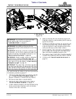
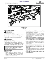
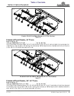
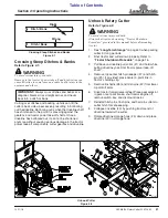
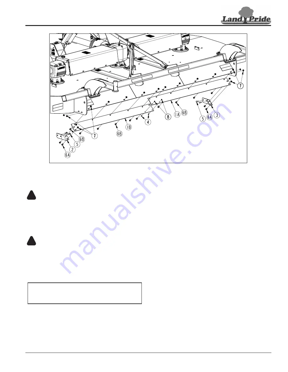
Rear Metal Guard

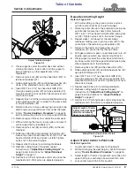
Figure 2-3

37162

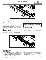
Rear Safety Guards

DANGER

!

To avoid serious injury or death:  
Rotary Cutters have the ability to discharge objects at high 

speeds; therefore, the use of front & rear safety guards is 

required and should always be used when cutting along 

roadways and in areas where bystanders are present. Stop 

blade rotation if bystanders are in or around the area.

WARNING

!

To avoid serious injury or death:  
Keep all safety guards in place. Rotary Cutters have the 

ability to discharge objects at high speeds. Use extreme 

caution when cutting in areas where people may be present. It 

is best to operate the cutter when no one is nearby. Stop blade 

rotation if someone is in or around the area.

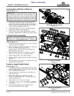
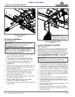
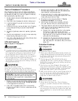
Rear Metal Guards

Refer to Figure 2-3:

1.

Attach left-hand bracket (#2) to the notched end of 
metal guard (#1B) as shown with 1/2"-13 x 1" GR5 
carriage bolts (#6A) and hex whiz nuts (#7). Do not 
tighten hex whiz nuts at this time.

NOTE:  

Do not tighten hardware until assemblies 

are complete. Refer to 

“Torque Values Chart” 

on 

page 46 for torque instructions.

2. Attach right-hand bracket (#3) to the notched end of 

metal guard (#1A) as shown with 1/2"-13 x 1" GR5 
carriage bolts (#6A) and hex whiz nuts (#7). Do not 
tighten hex whiz nuts at this time.

3. Attach right-hand metal guard (#1A) to the right-hand 

side of the deck with 1/2"-13 x 1" GR5 carriage bolts 
(#6B) and hex whiz nuts (#7). Do not tighten hex whiz 
nuts at this time.

4. Attach right-hand bracket (#3) to the right-hand side 

of the deck with 1/2"-13 x 1 1/2" GR5 carriage bolts 
(#5) and hex whiz nuts (#7). Do not tighten hex whiz 
nuts at this time.

5. Attach left-hand metal guard (#1B) to the left-hand 

side of the deck with 1/2"-13 x 1" GR5 carriage bolts 
(#6B) and hex whiz nuts (#7). Do not tighten hex whiz 
nuts at this time.

6. Attach left-hand bracket (#2) to the left-hand side of 

the deck with 1/2"-13 x 1 1/2" GR5 carriage bolts (#5) 
and hex whiz nuts (#7). Do not tighten hex whiz nuts 
at this time.

7.

Attach right and left-hand metal guards together with 
two 1/4"-20 x 3/4" GR5 carriage bolts (#4) and hex 
flange nuts (#8)

8. Tighten hex whiz nuts (#7) and hex flange nuts (#8) 

to the correct torque.

Summary of Contents for RCFM4014

Page 1: ...Decal Kit in French Language please see your Land Pride dealer Read the Operator s Manual entirely When you see this symbol the subsequent instructions and warnings are serious follow without exception Your life and the lives of others depend on it Rotary Cutter RCFM4014 326 730M Operator s Manual Printed 12 11 18 37149 ...

Page 2: ... the weights and measurements are no longer accurate for your machine Update the record by adding the machine weight and measurements provided in the Specifications Capacities Section of this manual with the Option s weight and measurements Dealer Contact Information Model Number Serial Number Machine Height Machine Length Machine Width Machine Weight Delivery Date First Operation Accessories Name...

Page 3: ...Equipment 20 Front Safety Guard Options 20 Front Rubber Guard 20 Front Chain Guard 20 Rear Safety Guard Options 21 Rear Metal Guard 21 Rear Rubber Guard 22 Rear Chain Guard 22 Shredder Fixed Blades 30 Rows 23 Shredder Fixed Blades 38 40 Rows 23 Shredder without Fixed Blades 24 Dish Pans With Cutter Blades 24 Section 3 Adjustments 25 Deck Height Level Adjustments 25 Level Deck Left to Right 25 Adju...

Page 4: ...ownload the appropriate App on your smart phone open the App point your phone on the QR code and take a picture Dealer QR Locator The QR code on the left will link you to available dealers for Land Pride products Refer to Parts Manual QR Locator on this page for detailed instructions RCFM4014 Rotary Cutter 326 730M Table of Contents See previous page for Table of Contents ...

Page 5: ...hildren to play on the power machine or implement Use extra caution when backing up Before the tractor starts to move look down and behind to make sure the area is clear Safety at All Times Careful operation is your best assurance against an accident All operators no matter how much experience they may have should carefully read this manual and other related manuals or have the manuals read to the...

Page 6: ... location Allow only enough slack in the chain to permit turning Always hitch the implement to the machine towing it Do not use the safety chain tow the implement Transport Safely Comply with federal state and local laws Use towing vehicle and trailer of adequate size and capacity Secure equipment towed on a trailer with tie downs and chains Sudden braking can cause a towed trailer to swerve and u...

Page 7: ...phones while operating equipment Use Seat Belt and ROPS Land Pride recommends the use of a CAB or roll over protective structures ROPS and seat belt in almost all power machines Combination of a CAB or ROPS and seat belt will reduce the risk of serious injury or death if the power machine should be upset If ROPS is in the locked up position fasten seat belt snugly and securely to help protect agai...

Page 8: ...ealer locator at www landpride com 3 Some new equipment installed during repair requires safety labels to be affixed to the replaced component as specified by Land Pride When ordering new components make sure the correct safety labels are included in the request 4 Refer to this section for proper label placement To install new labels a Clean the area where the label is to be placed b Spray soapy w...

Page 9: ...of Contents RCFM4014 Rotary Cutter 326 730M 12 11 18 5 838 614C 2 x 9 Red Reflector 2 places 37151 37151 37150 37150 838 603C 2 x 9 Orange Reflector 2 places 838 603C 2 x 9 Orange Reflector 2 places 838 614C 2 x 9 Red Reflector 4 places ...

Page 10: ...FM4014 Rotary Cutter 326 730M 8 11 14 6 818 681C Notice 20 MPH Max Travel Speed On all tires 838 615C 2 x 9 Amber Reflector 2 places 818 229C 1 3 4 x 2 3 4 Amber Reflector 2 places 37150 37152 37152 33016 33016 838 615C 2 x 9 Amber Reflector 2 places ...

Page 11: ...RCFM4014 Rotary Cutter 326 730M 12 11 18 7 838 603C 2 x 9 Orange Reflector 2 places Front Side of LED Light 37187 Back Side of LED Light 37187 Back Side of LED Light 37187 838 615C 2 x 9 Amber Reflector 2 places 838 614C 2 x 9 Red Reflector 2 places ...

Page 12: ...afety Information Table of Contents RCFM4014 Rotary Cutter 326 730M 8 11 14 8 37152 37152 37152 818 556C Danger Thrown Object 1 Place 818 714C Danger Crushing Hazard 1 Place 818 240C Caution 1000 rpm Only 1 Place ...

Page 13: ... Contents RCFM4014 Rotary Cutter 326 730M 12 11 18 9 37152 37152 37154 37154 818 552C Danger Rotating Driveline 2 Places 818 543C Danger Guard Missing Beneath gearbox input shaft shields 3 Places 818 142C Danger Rotating Driveline 1 Place ...

Page 14: ...rmation Table of Contents RCFM4014 Rotary Cutter 326 730M 8 11 14 10 818 564C Danger Rotating Blades 1 Place 37153 22296 22296 818 552C Danger Rotating Driveline 1 Place 818 540C Danger Guard Missing Do Not Operate 1 Place ...

Page 15: ... get years of satisfactory use from this Rotary Cutter Application The heavy duty RCFM4014 Rotary Cutters are designed and built by Land Pride to provide excellent cutting performance on gently sloping or slightly contoured right of ways pastures set aside acres or row crop fields Its 14 foot cutting width 2 to 12 cutting height and ability to cut weeds and brush up to 3 in diameter make it well s...

Page 16: ... and setup It is best to go through the Pre Assembly Checklist before assembling the cutter Speed up your assembly task and make the job safer by having all the needed parts and equipment readily at hand Gearbox Vented Dipsticks IMPORTANT Gearboxes are shipped with solid plugs in them to prevent oil loss during shipping and handling The solid plug on top of the gearbox must be replaced with a vent...

Page 17: ...itch pins 8 6 Insert hitch pins 8 into clevis holes as shown and secure with linchpins 9 Gearbox Input Shaft Shield Refer to Figure 1 5 1 If installing driveline remove shaft protector 4 from input shaft of gearbox 7 Do not remove if driveline will be installed at a later date 2 Unsnap one end of shield access doors 6 and rotate doors open 3 Attach shaft shield 5 to gearbox 7 with W10 1 5 x 20 GR8...

Page 18: ...olt 9 and nylock nut 11 Tighten nylock nut to the correct torque 37160 IMPORTANT Steps 2 3 below must be followed when tightening Lock nuts 10 IMPORTANT Discard hardware mounting tailwheel to shipping crate Use bolts flat washers and locknuts in bolt bag to mount tailwheel to cutter axle Driveline Installation Figure 1 6 Driveline Installation Refer to Figure 1 6 1 If not already done remove shaft...

Page 19: ...nuts in bolt bag to mount tailwheel to cutter axle Installation of End Tailwheels for 38 40 Rows Figure 1 9 End Tailwheels for 38 40 Rows Refer to Figure 1 9 When setting cutter up for 38 or 40 rows the center of the end tailwheels should be mounted 7 1 2 from each end of tool bar 4 for 38 rows and 3 1 2 from each end of toolbar for 40 rows Another way to measure it is 76 left and right of center ...

Page 20: ...s for this purpose 3 Remove lower linchpins 8 and hitch pins 2 Remove upper hairpin cotter 7 flat washer 6 hitch tube 4 and hitch pin 9 4 Slowly back tractor to cutter while using tractor s 3 point control lever to align lower 3 point arm hitch holes with clevis hitch pin holes 5 Shut tractor down properly Refer to Tractor Shutdown Procedure on this page 6 Attach lower 3 point arms to clevises wit...

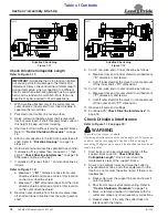
Page 21: ...nstructions see Main Driveline Slip Clutch on page 36 IMPORTANT Check driveline minimum collapsible length before completing Driveline Hook up Structural damage to the tractor and cutter can occur if this check is not made Refer to Check Driveline Collapsible Length on page 18 IMPORTANT The power take off shaft and gearbox input shaft must be aligned and level with each other when checking driveli...

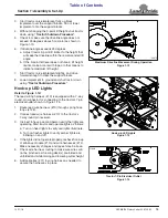
Page 22: ...etup when connecting to a different tractor and when alternating between using a quick hitch and a standard 3 point hitch More than one driveline may be required to fit all applications Driveline Shortening Figure 1 12 9 Cut off non yoke end of inner driveline as follows a Measure from end of inner shield to scribed mark X dimension and record b Cut off inner shield at the mark Cut same amount off...

Page 23: ...Hook up LED Lights Refer to Figure 1 14 The lead wiring harness 10 is equipped with a 7 way round pin connector for connecting to the tractor s 7 pin electrical outlet shown in Figure 1 15 1 Route lead wire harness 10 through spring hose loops 128 2 Connect lead wire harness 10 to the tractor s 7 way round pin receiver 3 It is best to have a second person verify the lights are operating Start trac...

Page 24: ...arge objects at high speeds therefore the use of front rear safety guards is required and should always be used when cutting along roadways and in areas where bystanders are present Stop blade rotation if bystanders are in or around the area WARNING To avoid serious injury or death Keep all safety guards in place Rotary Cutters have the ability to discharge objects at high speeds Use extreme cauti...

Page 25: ...whiz nuts at this time NOTE Do not tighten hardware until assemblies are complete Refer to Torque Values Chart on page 46 for torque instructions 2 Attach right hand bracket 3 to the notched end of metal guard 1A as shown with 1 2 13 x 1 GR5 carriage bolts 6A and hex whiz nuts 7 Do not tighten hex whiz nuts at this time 3 Attach right hand metal guard 1A to the right hand side of the deck with 1 2...

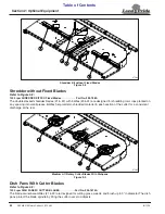
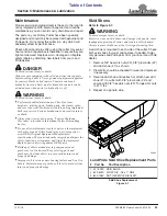
Page 26: ... whiz nuts 3 to the correct torque Rear Chain Guard Figure 2 5 Rear Chain Guards Refer to Figure 2 5 1 Locate chain guard 1 It does not have the extra chain strand 5 on one end as shown with chain guard 2 2 Attach left hand chain guard 1 to the left side of the deck rear with 1 2 13 x 1 1 4 carriage bolts 3 and hex whiz nuts 4 3 Attach right hand chain guard 2 to the right side of the deck rear wi...

Page 27: ...acing into small pieces Baffles help maintain shredded material in each section of the cutter for a consistent discharge at the rear Shredder Kit with Fixed Blades Designed for 38 40 Row Spacing Figure 2 7 Shredder Fixed Blades 38 40 Rows Refer to Figure 2 7 1000 rpm SHREDDER KIT 38 40 ROW Part No 326 715A The double stacked shredder blades 1 2 with stationary knives 3 4 7 and baffles 5 6 are desi...

Page 28: ...edding row crops planted on any spacing into small pieces Baffles help maintain shredded material in each section of the cutter for a consistent discharge at the rear Medium Lift Rotary Cutter Blades With Dishpans Figure 2 9 Dish Pans With Cutter Blades Refer to Figure 2 9 1000 rpm DISH PANS W CUTTER BLADES Part No 326 7675A The blade carrier assemblies 1 2 are designed for cutting grass weeds and...

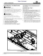
Page 29: ...tor Center 3 Point Link on page 28 Section 3 Adjustments Proper adjustment of each of these items will provide higher efficiency improved cutting performance and longer blade life Level Deck Left to Right Refer to Figure 3 1 The Rotary Cutter must operate level from side to side at all times Make certain tailwheels are adjusted to identical heights before adjusting lower 3 point lift arms See Adju...

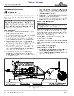
Page 30: ...er loss grass clumps blade wear and frequent blade sharpening 7 If rear blade is lower than the front blade or is more than 1 higher than the front blade then the tailwheel heights must be adjusted If needed see Adjust Tailwheel Height on page 27 8 Repeat steps 2 7 until tailwheel and 3 point arms are adjusted to the desired cutting height 9 Set tractor s 3 point hydraulic control stop once the ta...

Page 31: ...re 3 3 1 With cutter sitting on the ground remove nylock nut 8 and bolt 7B on the left tailwheel 2 Raise top collar 6 up to the preferred hole in yoke spindle 6 Secure top collar to that hole with 3 8 16 x 3 1 4 hex head bolt GR8 7B and nylock nut 8 Tighten nylock nut to the correct torque 3 Repeat steps 1 2 above for the remaining tailwheels making sure to pin top collar 6 to the same hole in the...

Page 32: ...t shields must be installed and in good working condition to avoid driveline entanglement and projectiles flying off of the driveline All guards and shields must be installed and in good working condition while operating the implement Never place hands or feet under the deck or attempt to make adjustments to the cutter with power take off engaged Cutter blades rotating at high speeds cannot be see...

Page 33: ... 34 The remaining inspections are made by engaging the power take off to check for normal operation WARNING To avoid serious injury or death Stop power take off immediately if vibration continues after a few revolutions during start up and anytime thereafter Wait for all components to come to a complete stop before dismounting from tractor to check for probable causes Make necessary repairs and ad...

Page 34: ...eath Clear area to be cut of debris and other unforeseen removable objects before cutting Mark non removable hazards such as tree stumps post stubs protruding objects rocks drop offs holes etc with a visible flag CAUTION To avoid minor or moderate injury Some tractors are equipped with two power take off speeds Do not exceed 1000 rpm power take off speed or equipment breakage may result 1 Thorough...

Page 35: ... across and never back into a ditch or bank Unhook Rotary Cutter Refer to Figure 4 2 WARNING To avoid serious injury or death Always shut tractor down using Tractor Shutdown Procedure provided in this manual before dismounting tractor 1 See Long Term Storage on page 40 when parking cutter for long periods 2 Shut tractor and cutter down properly Refer to Tractor Shutdown Procedure on page 16 3 Pull...

Page 36: ...iately to inspect the cutter Make necessary repairs before resuming operation It pays to inspect a new area and to develop a plan before you cut Normal mowing speed will be between 2 5 mph and you will need to maintain power take off speed to produce a clean cut so make a tractor gear and range selection that will maintain this combination Generally the quality of cut will be better at lower groun...

Page 37: ...this manual before dismounting tractor Do not alter implement or replace parts on the implement with other brands Other brands may not fit properly or meet OEM Original Equipment Manufacturer specifications They can weaken the integrity and impair the safety function performance and life of the implement Replace parts only with genuine OEM parts Buildup of debris around moving components and gearb...

Page 38: ... Make certain they are properly installed and in good working condition Replace any blade that is damaged worn bent or excessively nicked Small nicks can be ground out Cutter Blade Removal Refer to Figure 5 2 1 Shut tractor and cutter down properly Refer to Tractor Shutdown Procedure on page 16 2 Disconnect main driveline from tractor power take off and secure cutter deck in the up position with s...

Page 39: ...as tree stumps rocks and earth 37189 Face Beveled Edges of Flat Blade Down Blade Position and Direction of Rotation Figure 5 5 Cutter Blade Dish Pan Installation Refer to Figure 5 2 on page 35 1 Be sure to read Important Notes under Blade Installation on this page before installing blades 2 Insert blade bolt 1 through blade 6 dish pan 4 and flat washer 2 Secure blade with a new 1 1 8 12 hex top lo...

Page 40: ... is clear of all bystanders and the implement is safe to operate 4 Start tractor and engage power take off drive for 2 3 seconds to permit slippage of the clutch surfaces Disengage power take off then re engage a second time for 2 3 seconds Disengage power take off shut off tractor and remove key Wait for all components to stop before dismounting from tractor 5 Inspect clutch and ensure that the s...

Page 41: ...ch spring retainer bolt until correct spring height A is reached Clutch Disassembly Assembly Figure 5 8 IMPORTANT Not all clutches are assembled the same with the same number of components Be sure to keep track of order and orientation of your clutch components during disassembly 23554 Intermediate Drivelines Refer to Figure 5 9 Intermediate Driveline Maintenance Figure 5 9 Intermediate Driveline ...

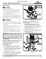
Page 42: ...n hose A coating of oil may also be applied to the lower deck area to minimize oxidation 2 Check blades and blade bolts Replace if needed See Cutter Blades on page 34 3 Inspect for loose damaged or worn parts Adjust or replace parts as needed 4 Repaint parts where paint is worn or scratched to prevent rust Ask your Land Pride dealer for aerosol touch up paint Paint is also available in touch up bo...

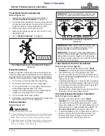
Page 43: ...wheel Zerk can be on either side as shown Type of Lubrication Multi Purpose Grease Quantity 2 pumps 24 Hours 24 Hours 37176 26537 Outside Location Inside Location 37177 Pivot Shaft for Optional Warning Lights Type of Lubrication Spray Lubricant Quantity As needed 30 Hours 50 Hrs Multi purpose spray lube Multi purpose grease lube Multi purpose oil lube Intervals in hours at which lubrication is req...

Page 44: ...le add recommended gear lube through top dipstick hole until oil flows out of side plug hole Reinstall and tighten side oil plug 2 and vented dipstick 1 Type of Lubrication 80 90W EP Gear Lube Quantity Fill until oil reaches top mark on dipstick or begins to flow out side plug hole in gearbox NOTE Do not overfill Cutter should be level when checking oil Oil expands when hot therefore always check ...

Page 45: ...Multi Purpose Grease Quantity 6 pumps Main Driveline U Joints Type of Lubrication Multi Purpose Grease Quantity 6 pumps 8 Hours Intermediate Driveline U Joints Type of Lubrication Multi Purpose Grease Quantity 6 pumps Main Driveline Profile Type of Lubrication Multi Purpose Grease Quantity 6 pumps 20 Hours 8 Hours 40 Hours 13755 13755 37176 37176 ...

Page 46: ...n flat washer and locknut Blade tip speed At center T box At outboard gearboxes 15 000 FPM 15 000 FPM Driveline protection Main Intermediate 1000 rpm 4 plate slip clutch Cat 5 Spring loaded flex coupler Options Blade options Dish pan Shredder kit 30 row Shredder kit 38 40 row Shredder kit w o fixed blades 1 2 x 4 Heat treated free swinging suction blades with 3 16 round stump jumper Double stacked...

Page 47: ...Section 6 Specifications Capacities Table of Contents RCFM4014 Rotary Cutter 326 730M 12 11 18 43 37178 3 11 1 4 MIN 4 10 1 4 MAX 14 6 1 2 10 0 1 2 ...

Page 48: ...objects Round back design Allows for cleaner and efficient discharge of material helps eliminate damage to rear corners by not sticking out Full length skids with reversible replaceable shoes Adds reinforcement to side panels Reversible and replaceable skid shoes allow for change before wearing through to weld on piece Laminated tires Laminated tires can handle almost any condition and don t go fl...

Page 49: ...ermediate Drivelines on page 38 Shaft clamping cotter bolt is shearing Not greasing telescoping tubes Grease telescoping tubes every 40 hours See Intermediate Drivelines on page 38 Blades wearing excessively Cutting on sandy ground Raise cutting height Contacting ground frequently Raise cutting height Blades breaking Hitting solid objects Avoid hitting solid objects Blades hitting each other Blade...

Page 50: ...40 180 335 245 5 8 18 150 110 230 170 325 240 M18 X 2 5 195 145 310 230 405 300 3 4 10 235 170 360 265 510 375 M18 X 1 5 220 165 350 260 485 355 3 4 16 260 190 405 295 570 420 M20 X 2 5 280 205 440 325 610 450 7 8 9 225 165 585 430 820 605 M20 X 1 5 310 230 650 480 900 665 7 8 14 250 185 640 475 905 670 M24 X 3 480 355 760 560 1050 780 1 8 340 250 875 645 1230 910 M24 X 2 525 390 830 610 1150 845 ...

Page 51: ...ose for which the product is not designed Misuse also specifically includes failure to properly maintain oil levels grease points and driveline shafts Claims under this Warranty should be made to the dealer which originally sold the product and all warranty adjustments must be made through an authorized Land Pride dealer Land Pride reserves the right to make changes in materials or design of the p...

Page 52: ...Corporate Office P O Box 5060 Salina Kansas 67402 5060 USA www landpride com ...

Reviews: