Section 3: Adjustments
RCFM4014 Rotary Cutter 326-730M
12/11/18
27
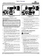
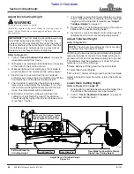
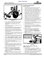
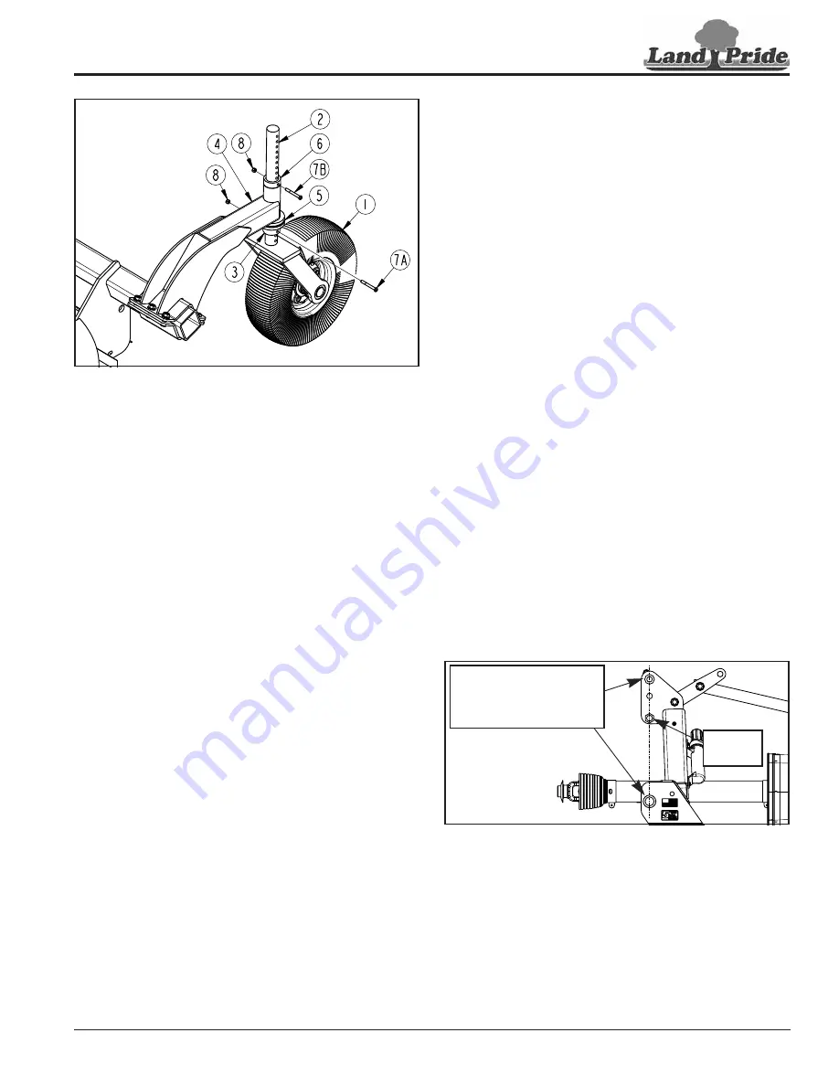
Adjust Tailwheel Height
Figure 3-3
3. Place supports under the cutter deck and without
starting the tractor, lower cutter onto the supports
before making any other adjustments to the
tailwheels.
4. Remove nylock nut (#8) and hex head bolt (#7A) in
left-hand tailwheel (#1).
5. Slide adjusting collar (#3) and tailwheel washer (#5)
down to the preferred hole in yoke spindle (#6).
6. Insert 3/8"-16 x 3 1/4" hex head bolt GR8 (#7A)
through adjusting collar (#3) and yoke spindle (#2).
Secure bolt with nylock nut (#8). Tighten nylock nut to
the correct torque.
7.
Repeat steps 1-6 for the remaining tailwheels making
sure adjusting collar (#3) is pinned to the same hole
in all yoke spindles (#2).
8. Return to tractor to raise cutter up high enough to be
able to remove support blocks from under the deck.
9. Follow
before dismounting tractor to remove support blocks.
10. Remove support blocks from under the cutter deck.
11. Without starting the tractor, lower cutter until rear of
unit is supported by tailwheels (#1).
12. Remove nylock nut (#8) and bolt (#7B) on the left
tailwheel.
13. Slide top collar (#6) down against trailing arm (#4).
Secure top collar to that hole with 3/8"-16 x 3 1/4" hex
head bolt GR8 (#7B) and nylock nut (#8). Tighten
nylock nut to the correct torque.
14. Repeat step 13 above for remaining tailwheels.
15. Recheck cutting height. If required, repeat
instructions for
page 26 and instructions for
16. Set tractor’s 3-Point hydraulic control stop once the
tailwheel and 3-Point arms are adjusted properly.
37170
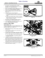
Raise Deck Cutting Height
1.
With cutter sitting on the ground, remove nylock
nut (#8) and bolt (#7B) on the left tailwheel.
2. Raise top collar (#6) up to the preferred hole in yoke
spindle (#6). Secure top collar to that hole with
3/8"-16 x 3 1/4" hex head bolt GR8 (#7B) and nylock
nut (#8). Tighten nylock nut to the correct torque.
3. Repeat steps 1 & 2 above for the remaining
tailwheels making sure to pin top collar (#6) to the
same hole in the remaining yoke spindles (#2).
4. Return to the tractor and raise cutter up until
tailwheels (#1) are carried by the top collars.
5. With gear selector in park or park brake set; turn off
engine, remove switch key, and dismount tractor.
6. Place supports under the cutter deck. Start tractor
and lower cutter onto the supports before making any
other adjustments to the tailwheels.
7.
Remove nylock nut (#8) and hex head bolt (#7A).
8. Slide adjusting collar (#3) and tailwheel washer (#5)
up against trailing arm (#4).
9. Insert 3/8"-16 x 3 1/4" hex head bolt GR8 (#7A)
through adjusting collar (#3) and yoke spindle (#2).
Secure bolt with nylock nut (#8). Tighten nylock nut to
the correct torque.
10. Repeat step 9 above for remaining tailwheels.
11. Recheck cutting height. If required, repeat
instructions for
page 26 and instructions for
12. Set tractor’s 3-Point hydraulic control stop once the
tailwheel and 3-Point arms are adjusted properly.
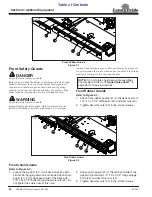
Adjust Tractor Center 3-Point Link
Figure 3-4
Adjust Tractor Center 3-Point Link
1.
Lower cutter deck to the preset cutting height.
2. Without changing the deck height, shut tractor down
using
3. Adjust length of tractor’s top center 3-point link until
upper hitch pin is vertically above lower hitch pins.
4. Lock center 3-point link in this position.
37171
Adjust Length of Center
3-Point Link Until Upper
Hitch Pin is Vertically
Above Lower Hitch Pins.
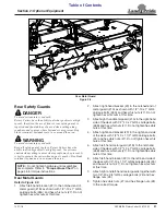
Bolt-on
Bushing

