Section 5: Maintenance & Lubrication
RCFM4014 Rotary Cutter 326-730M
12/11/18
35
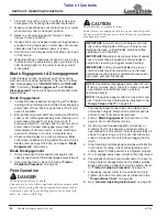
Fixed Blade Removal (Optional)
1.
Shut tractor and cutter down properly. Refer to
2. Disconnect main driveline from tractor power take-off
and secure cutter deck in the up position with solid
supports before servicing underside of cutter.
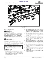
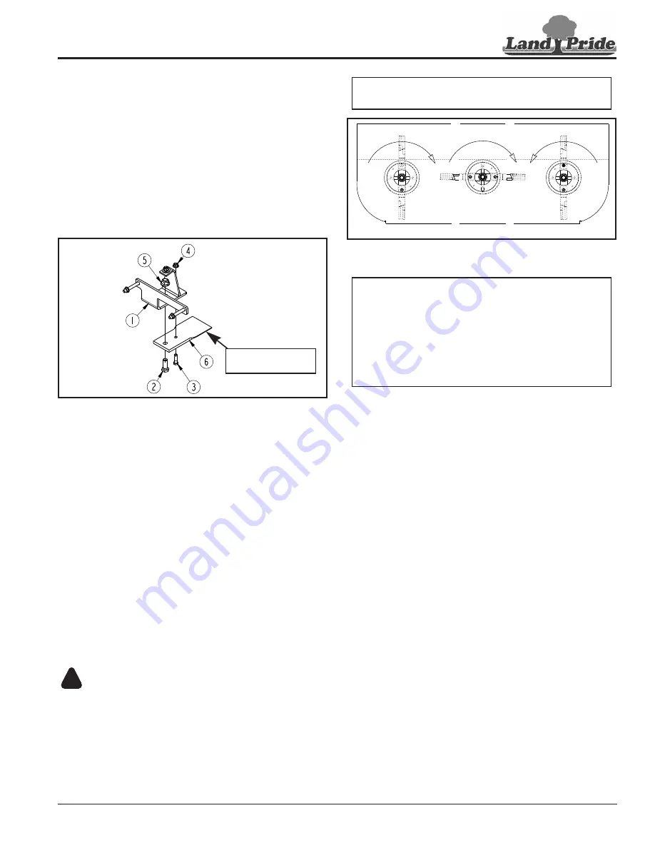
3. Remove hex whiz nut (#4) and bolt (#3).
4. Remove hex flange top locknut (#5), bolt (#2), and
fixed blade (#6).
5. Go to
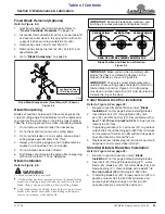
Fixed Blade Components (Front Mount (#1) Shown)
Figure 5-4
Blade Sharpening
Blades should be sharpened at the same angle as the
original cutting edge. Paired blades must be replaced or
re-ground at the same time to maintain proper balance.
Take the following precautions when sharpening blades:
1.
Do not remove more material than necessary.
2. Do not heat and/or pound out a cutting edge.
3. Do not grind blades to a razor edge. Leave a blunt
cutting edge approximately 1/16" thick.
4. Always grind cutting edge so end of blade remains
square to cutting edge and not rounded.
5. Do not sharpen back side of blade.
6. Both blades should weigh the same after sharpening
with not more than 1 1/2 oz. difference.
Blade Installation
WARNING
!
To avoid serious injury or death:
•
A locknut that has been removed can lose its thread locking
properties. Reusing a used locknut can result in a thrown
blade. Always use a new locknut when installing blades.
•
Cutter blades must be 90 deg. to each other to be in time or
blades will contact each other when hitting solid objects
such as tree stumps, rocks and earth.
37189
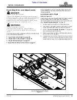
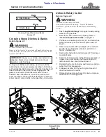
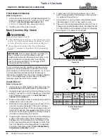
Face Beveled Edges
of Flat Blade Down
Blade Position and Direction of Rotation
Figure 5-5
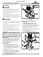
Cutter Blade & Dish Pan Installation
Refer to Figure 5-2 on page 35:
1.
Be sure to read Important Notes under
on this page before installing blades.
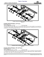
2. Insert blade bolt (#1) through blade (#6), dish
pan (#4), and flat washer (#2). Secure blade with a
new 1 1/8"-12 hex top locknut (#3)
. Torque hex top
locknut to 450 ft-lbs.
3. If replacing dishpan (#4), castle nut (#7) on gearbox
output shaft should be torqued to 550 ft-lbs minimum
and secured with cotter pin (#8) with both legs bent
opposite directions around the nut.
4. Replace access rubber plug (#5) and reconnect main
driveline to tractor power take-off shaft.
Shredder Blade & Blade Bar Installation
Refer to Figure 5-3 on page 35:
1.
Be sure to read instructions under
on this page before installing blades.
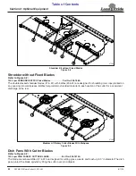
2. Insert bolt (#3) through blade bushing (#1), cutter
blade (#5), blade bar (#2), flat cutter blade (#6), and
blade bushing (#1). Secure blade with a
new 1"-8
hex top locknut (#4)
and torque to 450 ft-lbs.
3. If installing blade bar (#2), torque castle nut (#8) on
gearbox output shaft to 550 ft-lbs minimum and
secure by bending both legs of cotter pin (#9)
opposite directions around the castle nut.
IMPORTANT:
Examine blade bolts, washers, and
bushings for excessive wear and replace if worn.
CW ROTATION
CCW ROTATION
CW ROTATION
REAR OF CUTTER VIEWED FROM THE TOP
37173
IMPORTANT:
Make certain when installing cutter
blades that they are rotated 90 degrees to the
adjacent blades as shown in Figure 5-5.
IMPORTANT:
To ensure correct blade placement,
carefully check cutting edges of blades in relation to
blade rotation shown in Figure 5-5. Cutting edge
must lead in rotation and airfoil (lift) must be oriented
towards the top of the deck.

