Section 5: Maintenance & Lubrication
RCFM4014 Rotary Cutter 326-730M
12/11/18
37
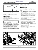
Clutch Disassembly, Inspection & Assembly
If clutch run-in procedure above indicated that one or more
friction disks did not slip, then the clutch must be
disassembled to separate the friction disks.
Disassembly
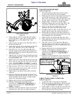
Disassembly of clutch is simply a matter of first removing
spring retainer nuts (#1), springs (#2), and bolts (#3) from
the assembly. Each friction disk (#4) must then be
separated from the metal surface adjacent to it.
Inspection
Inspect all parts for excessive wear and condition. Clean
all parts that do not require replacement.The original
friction disk thickness is 1/8" (3.2mm) and should be
replaced if thickness falls below 3/64" (1.1mm). If
clutches have been slipped to the point of “smoking”, the
friction disks may be damaged and should be replaced.
Heat build-up may also affect the yoke joints.
Assembly
Reassemble each friction disk (#4) next to the metal plate
it was separated from. Install bolts (#3) through the end
plates and intermediate plates as shown. Place springs
(#2) over the bolts and secure with nuts (#1).
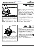
Refer to Figure 5-7 on page 37:
Progressively tighten each spring retainer bolt until
correct spring height “A” is reached.
Clutch Disassembly/Assembly
Figure 5-8
IMPORTANT:
Not all clutches are assembled the
23554
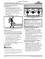
Intermediate Drivelines
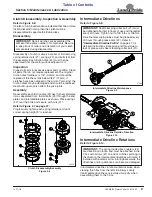
Intermediate Driveline Maintenance
Figure 5-9
Intermediate Driveline Rotation Direction
Figure 5-10
Intermediate Driveline Rotations
Intermediate drivelines rotate counterclockwise when
viewing the T-box from the left side. Always verify
intermediate drivelines are installed correctly when
assembling them to the T-box.
IMPORTANT:
Shaft clamping cotter bolt (#1) must
be tightened after first 8 hours of use and thereafter
every 40 hours. Tighten nut to 100 ft-lbs or 136 Nm.
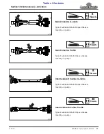
Driveline telescoping tubes must be greased every
40 hours through grease zerk (#2). Refer to
“Intermediate Driveline Profile”
detailed instructions. Excessive end thrust due to
lack of grease will shear clamping cotter bolt (#1).
37186
37214
IMPORTANT:
The spring loaded flex couplers (#2)
are directional rotation and must be attached to the
T-box with arrows (#1) on end of clutches pointing in
the direction the intermediate drivelines will rotate. If
installed with indicator arrow rotating backwards, the
drivelines and/or gearboxes can become damaged.

