15
Section 1: Assembly and Set-Up
2/03/12
RCR1884 Series Rotary Cutter 312-880M
Table of Contents
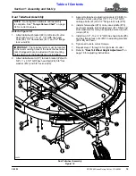
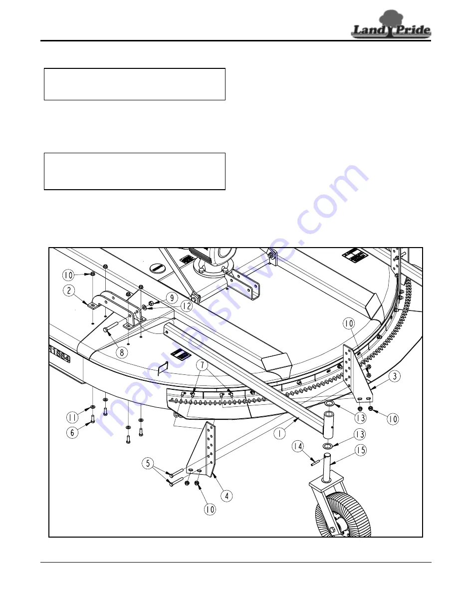
Dual Tailwheel Assembly
Refer to Figure 1-8:
1.
Attach tailwheel bracket (#2) to left side of cutter
deck with four 1/2" -13 x 1 1/2" GR5 hex head
bolts (#6), 1/2" flat washers (#11) and 1/2" flange
lock nuts (#9).
2.
Attach tailwheel arm (#1) to deck bracket (#2) with
5/8"-11 x 3 1/4" GR5 hex head bolt (#8), 5/8" flat
washer (#12) and 5/8" lock nut (#9).
NOTE: Do not tighten hardware until assembly
is complete. See “Torque Values Chart” on page
34 for correct torques.
IMPORTANT: The tailwheel arms must be located
in the rear mounting holes of the deck channel when
rear chainguards are included and front mounting
holes when rear chainguards are not included.
3.
Assemble tailwheel adjusting brackets (#3 & #4) to
left side of deck using four 1/2"-13 x 1 1/2" GR5
carriage bolts (#7) and 1/2" flange lock nuts (#10).
4.
Install shim washer (#13) onto yoke spindle (#15)
and insert spindle into tailwheel arm (#1). Slide 2nd
shim washer (#13) onto yoke spindle and secure with
roll pin (#14).
5.
Install two 1/2" -13 x 3 1/2" GR5 hex head bolts (#5)
and hex flange lock nuts (#10) in adjusting brackets
(#3 & #4) as shown.
6.
Tighten all nuts to correct torque.
7.
Repeat steps 1 through 6 for right side of cutter.
8.
Refer to “Dual Tail Wheel Height Adjustment” on
page 19 for adjusting instructions.
Dual Tailwheel Assembly
Figure 1-8
24665


