


Alle Angaben verstehen sich als unverbindliche Richtwerte! Für nicht schriftlich bestätigte Datenauswahl übernehmen wir keine Haftung. Druckangaben beziehen sich, soweit nicht anders angegeben, auf Flüssigkeiten der Gruppe II bei +20°C.
11
Dokumentation
VORTEX-Rohre
MAIL:
verkauf@landefeld.de ·
TEL:
(05 61) 9 58 85 - 9 ·
FAX:
(05 61) 9 58 85 - 20
To fit the VORTEX 14 CC follow the steps below:
A. Drill Hole
Drill 1.02” (26 mm) hole in the position you would like to fit the VORTEX 14 CC.
Please be aware that 200mm of the VORTEX 14 CC will extend from the outside of the enclosure so allow clearance.
It’s recommended that the VORTEX 14 CC is installed in the top of the enclosure. However, if space is an issue the VORTEX 14 CC can be installed in any posi-
tion, even upside down, with no loss of performance.
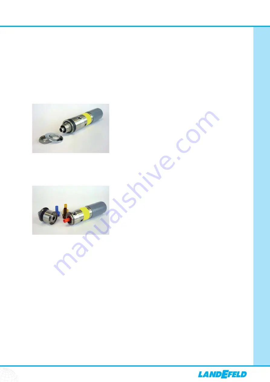
B. Remove bulk head nut & washer from the bottom of the VORTEX 14 CC:
C. Fit desired generator
As standard the VORTEX 14 CC is supplied with a red (Refrig) 15cfm, 293W (1000 Btu/hr) generator. To change the generator simply unscrew the bulk head fitting
and replace the generator with another colour. Please remember to re-fit the o-ring and screw bulk head fitting until tight.
Four generators are provided with the VORTEX 14 CC. Information on all generators and sizing can be found in section 10.6.
D. Fit VORTEX 14 CC in place
From outside the enclosure, place the cold end of the VORTEX 14 CC into the drilled hole.
E. Re-fit bulk head nut and washer
Once this is done tighten bulk head nut & washer until the VORTEX 14 CC is secure.
F. Connect cold air ducting to the end.
It’s recommended that the cold air ducting is directed from the VORTEX 14 CC to the bottom of the enclosure. This will allow for increased cooling throughout the
cabinet/panel. This will also avoid any excess water vapour in the compressed air being blown over components.
If the air is clean and dry the cold air ducting can be directed to particularly hot areas of the enclosure. Alternatively you can drill holes in the cold air ducting and
allow air to be distributed to several areas. If you choose this method you will need to plug the end of the cold air ducting and ensure the holes drilled into the
tube are equal to the hole at the end.
Where necessary please fit appropriate filters.
G. Connect air supply
The VORTEX 14 CC has a ¼” bsp female air inlet. Standard pneumatic push-fit compressed air fittings can be used on the VORTEX 14 CC.
Please refer to section 10.4 when deciding on pipe sizes.
H. Connect the digital thermostat & solenoid valve to the air
supply (only with VORTEX 14 CC System) See section 10.7 of this operating manual. Your VORTEX 14 CC is now ready for use.


