Alle Angaben verstehen sich als unverbindliche Richtwerte! Für nicht schriftlich bestätigte Datenauswahl übernehmen wir keine Haftung. Druckangaben beziehen sich, soweit nicht anders angegeben, auf Flüssigkeiten der Gruppe II bei +20°C.
13
Dokumentation
VORTEX-Rohre
MAIL:
verkauf@landefeld.de ·
TEL:
(05 61) 9 58 85 - 9 ·
FAX:
(05 61) 9 58 85 - 20
A VORTEX 14 CC System is supplied with either a 24V or 230V digital thermostat and solenoid valve.
The combination of solenoid valve and digital thermostat allows application specific set up and reduces running costs. It means cold air will only be supplied to the
enclosure when it’s needed.
The digital thermostat is factory set to activate the VORTEX 14 CC when the internal cabinet/panel temperature reaches 30°C. It will then cool the enclosure until
the temperature drops to 22°C. At this point the VORTEX 14 CC is deactivated ready for the process to start again.
Adjustment of Factory settings
The thermostat is password protected to stop adjustment of the parameters. The following 3 steps explain how to unlock the thermostat for parameter adjustment.
1. Power up thermostat – the temperature will be displayed.
2. Press and hold the ‘P’ until a ‘0’ is displayed (when 0 is displayed release the ‘P’ button)
3. Press and hold the
˄
button until the display shows 9000. Press ‘P’ once, you will now have access to change the parameters.
Adjusting the main parameters
There are 2 main parameters that you may wish to adjust; the Set Point and Differential. The following 5 steps will guide you though this process.
1. Use the 2 arrow buttons to toggle through the parameters.
2. When you reach ‘SP’ on the display stop and press the ‘P’ button once. This allows you to adjust the set point of the thermostat between 10 and 50. The Set
Point is the temperature that once activated the system will cool the cabinet/panel to (factory set to 22°C).
3. Once you have entered your Set Point press the ‘P’ button once. This will activate the new setting and return you to the main toggle menu.
4. Using the 2 arrow buttons toggle through the parameters until you reach ‘HSEt’.
5. When you have reached ‘HSEt’ press the ‘P’ button once. This allows youto adjust the differential of cooling. The differential is the number of degrees above the
set point that the unit will cool from (factory set to 8°C above a set point of 22°C, meaning the unit will start cooling when the internal cabinet temperature reaches
30°C).
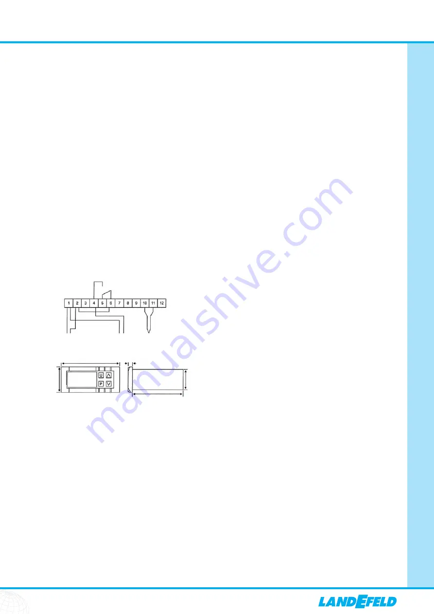
Ther
m
ostat Wiri
n
g Diagra
m
:
Ther
m
ostat Di
m
e
n
sio
n
s:
75
mm
64
mm
28
mm
33
mm
5
mm
NO
N
Power
Sole
n
oid Valve
Probe
L
N
L
Brow
n
Blue
NC C
10.7 Magnetventil & Thermostat (nur VORTEX 14 CC ... System) / Solenoid Valve & Thermostat (VORTEX 14 CC ... System Only)
The VORTEX 14 CC is IP56 (Nema 4/12)
Air flow
Problems with compressed air flow can be caused by:
1. Air pressure too low – increase air pressure at the relevant regulator
2. Undersized compressed air lines – replace pipes with correct sizes, see section 10.4
3. Blocked compressed air line – remove blockage
4. Insufficient compressor size – Check compressor size for fitting VORTEX 14 CC
Air Temperature
Problems with air temperature can be caused by:
1. Incorrect generator fitted – Check and replace generator, see section 10.6
2. Ambient compressed air temperature too high – Check compressed air temperature and use cooler if necessary
3. Loose/missing parts – Check all VORTEX 14 CC parts are screwed in tightly and there are no missing parts.
4. Water vapour in the compressed air supply – Check compressed air supply
5. Air pressure too low – increase air pressure at the relevant regulator
10.8 Approvals
10.9 Troubleshooting


