Alle Angaben verstehen sich als unverbindliche Richtwerte! Für nicht schriftlich bestätigte Datenauswahl übernehmen wir keine Haftung. Druckangaben beziehen sich, soweit nicht anders angegeben, auf Flüssigkeiten der Gruppe II bei +20°C.
8
Dokumentation
VORTEX-Rohre
MAIL:
verkauf@landefeld.de ·
TEL:
(05 61) 9 58 85 - 9 ·
FAX:
(05 61) 9 58 85 - 20
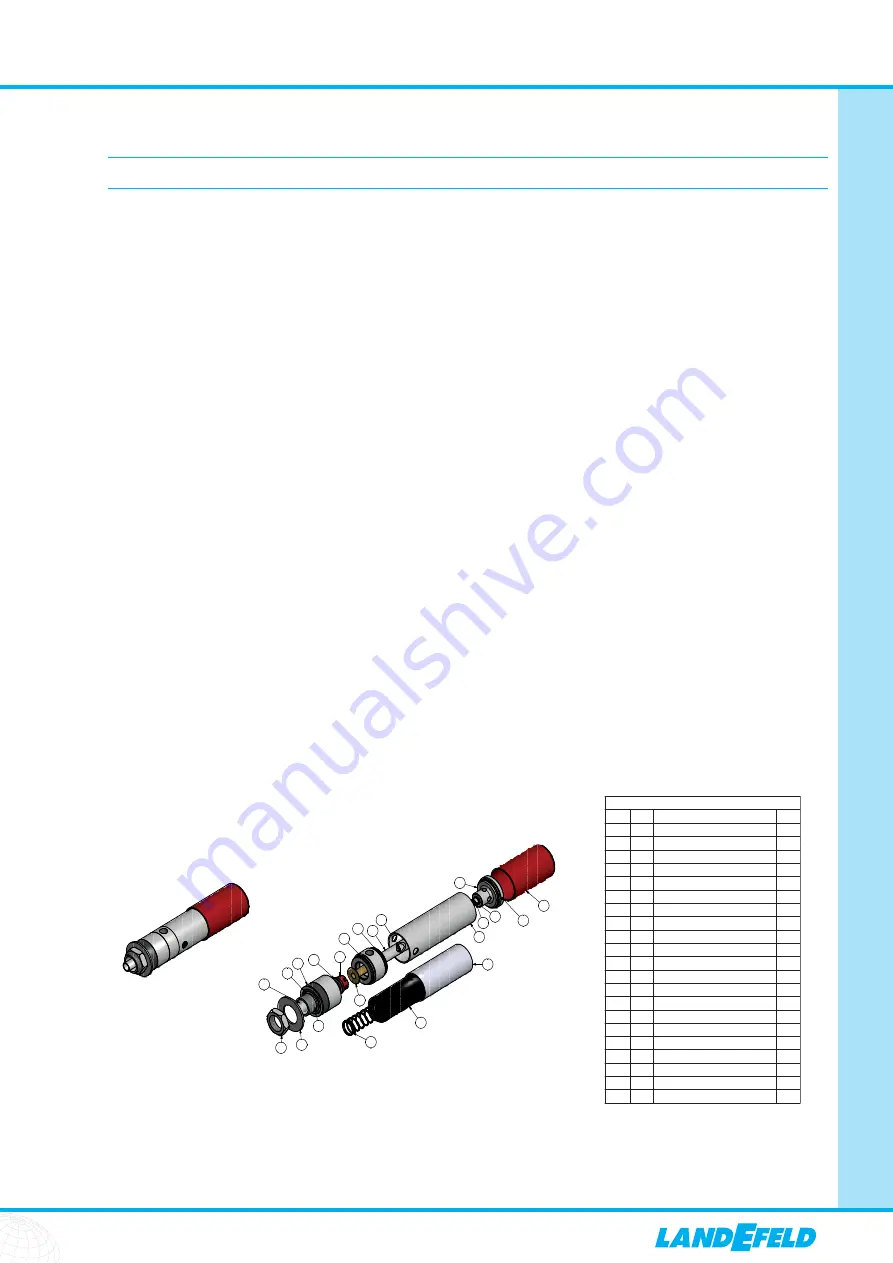
10. Bedienungsanleitung VORTEX 14 CC / Operating Manual VORTEX 14 CC
The VORTEX 14 CC uses compressed air to provide a cold air source which stops industrial cabinet/panels or enclosures overheating and prevents ingress of con-
tamination such as dust or moisture.
The VORTEX 14 CC Unit (excluding Solenoid Valve and Thermostat) is intrinsically safe, and requires virtually no maintenance. They have no moving parts making
them ideal for harsh environments.
VORTEX 14 CC can be used with or without electrical thermostats and solenoid valves (VORTEX 14 CC System). These are used to regulate the cooling within an
enclosure.
VORTEX 14 CC are packed carefully at our factory. Nevertheless, we recommend careful examination of the carton and contents for any damage.
To protect yourself and others when using compressed air, you should be aware of the following general safety guidelines:
‧
Warning – When compressed air is misused, it can cause serious injury or even death.
‧
Never point an air hose at anyone in fun or to remove dirt from clothing or the body.
‧
Never use compressed air without adequate eye and ear protection. Use safety glasses with side shields or goggles and ear protectors.
‧
Before attempting to disconnect a hose from an air line, the air should be cut off, and the remaining air bled from the line.
‧
Keep air hoses off the floor where they become tripping hazards and are subject to damage by vehicles, doors, and dropped tools. If possible, suspend air
hoses from overhead.
Please be aware of the following safety guidelines specific to the VORTEX 14 CC:
‧
VORTEX 14 CC create both hot and cold air so parts of the unit will become hot.
‧
Do not operate the VORTEX 14 CC at compressed air pressures above 11 Bar (160 psi)
‧
Compressed air temperature must not exceed 55°C
‧
Ambient operating temperature must not exceed 66°C
‧
Ambient operating temperature can not drop lower than -10°C
4
5
1
7
2
3
6
Exploded
View
16
18
10
9
8
12
13
3
16
16
17
11
22
21
23
REV
PARTS LIST
ITEM QTY
PART NUMBER
B
A
1
1 Spi
n
Cha
m
ber
A
2
1 Ge
n
erators (See Drawi
ng
)
A
3
1 Bulkhead Fitti
ng
B
4
1 Hot E
n
d Cap
B
5
1 Hot E
n
d Sleeve
A
6
1 Needle Valve
A
7
1 Brass Sleeve
A
8
1 Sile
n
cer Spri
ng
A
9
1 Sile
n
cer Foa
m
10
1 Plastic I
n
sert
11
1 Star Washer
12
1 Bulk Head Washer
A
13
1 Bulkhead Nut 33
mm
B
17
1 O Ri
ng
17x3
mm
A
18
1 O Ri
ng
3/8x1/4
A
19
1 O Ri
ng
30x3
mm
A
1
20
Bli
n
d Rivet 3.2 x 4.8
mm
21
1 Relief Valve
A
22
1 Red E
n
d Cap
A
23
1 Bulk Head I
n
sert
A
A
3
16
O Ri
ng
The VORTEX 14 CC has no moving parts. Clean compressed air moving through the will not cause wear on any of the components.
Occasionally, dirt, water or oil may enter the cooler from the compressed air supply. This could hinder the performance. If this happens simply take the unit apart,
clean the parts with soapy water, allow drying time and then reassemble.
When reassembling ensure you tighten all the components. If the parts are not tightened correctly, the coolers performance may be affected. Also, please ensure
the generator is fitted. At the same time the element in the air filter should be changed.
10.1 Safety and Inspection
10.2 Maintenance


