105
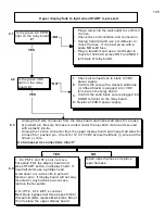
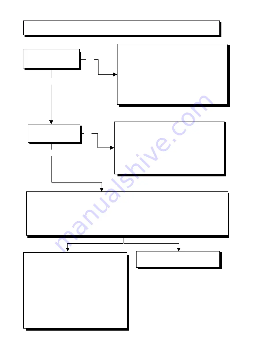
Upper display fails to light when START is pressed.
Is the green AC PW R
light on the relay board
lit?
1. Plug a lamp into the wall outlet to confirm it
it is live.
2. Check line cord condition and connection.
3. Unplug treadmill and use a multimeter to
check the fuse. If it is bad, swap with a
spare MDA-20 fuse.
4. Plug in treadmill and use a multimeter to
check for 120VAC across HOT and NEUT
terminals of relay board.
1.
Check all connections to black 12VDC
power supply.
2.
Confirm the wire with a dashed white line
(or ribbed black) is plugged into +VDC
terminal on the relay board.
3.
Confirm the solid black wire is plugged into
SGND terminal on the relay board.
4.
Replace 12VDC power supply.
1. Unplug the 9 wire connector from the relay board and inspect all wires for a loose
or pushed pin. Be sure harness is routed under the elevation motor and secured
with a plastic zip-tie.
2. Unplug the 12 wire connector from the upper display board and inspect all wires for
a loose fit or pushed pin. Check for 12 to 15VDC across the Black (+) wire and the
Green (-) wire.
Are harness wire connections intact?
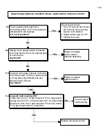
Is the green VDC
light on the relay
board lit?
4.1
4.2
4.3
4.4
YES
NO
YES
NO
1. On PST’s and ST’s only, remove
Faceplate from the display board and
press START button on display board. If
treadmill starts use a phillips head
screwdriver or x-acto knife to spread
fastener pins. If display board will not stay
mounted or any buttons are concave
replace the faceplate.
2. On PT’s, CT’s & ET’s conduct
Membrane bypass test (See pages 63,64)
If treadmill starts replace Membrane Panel.
If not replace the upper display board.
Repair upper harness or replace
upper harness.
YES
NO
Summary of Contents for Cardio Trainer L8
Page 5: ...5 ...
Page 27: ...27 Section 3 Parts Identification L8 L9 BED EXPLODED VIEW 18 ...
Page 28: ...28 L7 BED EXPLODED VIEW L Series Upright ...
Page 29: ...29 L SERIES UPRIGHT EXPLODED VIEW 112 ...
Page 30: ...30 L SERIES MOTOR PAN EXPLODED VIEW 111 ...
Page 35: ...35 COMMERCIAL MOTOR PAN SCR MOTOR CONTROL BOARD ...
Page 36: ...36 L SERIES 110V COMMERCIAL LOWER WIRE SCHEMATIC ...
Page 37: ...37 L SERIES 220V COMMERCIAL LOWER WIRE SCHEMATIC ...
Page 40: ...40 L SERIES SCR UPPER WIRE HARNESS WIRING DIAGRAM ...
Page 42: ...42 L SERIES HOME MOTOR PAN WIRING SCHEMATIC ...
Page 47: ...47 L SERIES HOME MOTOR PAN WIRING SCHEMATIC PWM MOTOR CONTROL BOARD W RELAY ASSEMBLY ...
Page 48: ...48 PWM MOTOR CONTROL BOARD W RELAY ASSEMBLY ...
Page 49: ...49 L SERIES PWM UPPER WIRE HARNESS WIRING DIAGRAM ...
Page 50: ...50 EXECUTIVE TRAINER LCD WIRING SCHEMATIC ...
Page 110: ...110 L SERIES ROAD RUNNER LOWER WIRING DIAGRAM ...
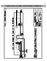
Page 111: ...111 L SERIES ROAD RUNNER UPPER WIRING SCHEMATIC ...


