112
ROAD RUNNER SUPPLEMENTAL ASSEMBLY INSTRUCTIONS
(Follow these instructions in conjunction with Step 10 on page 3 of your manual.)
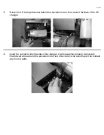
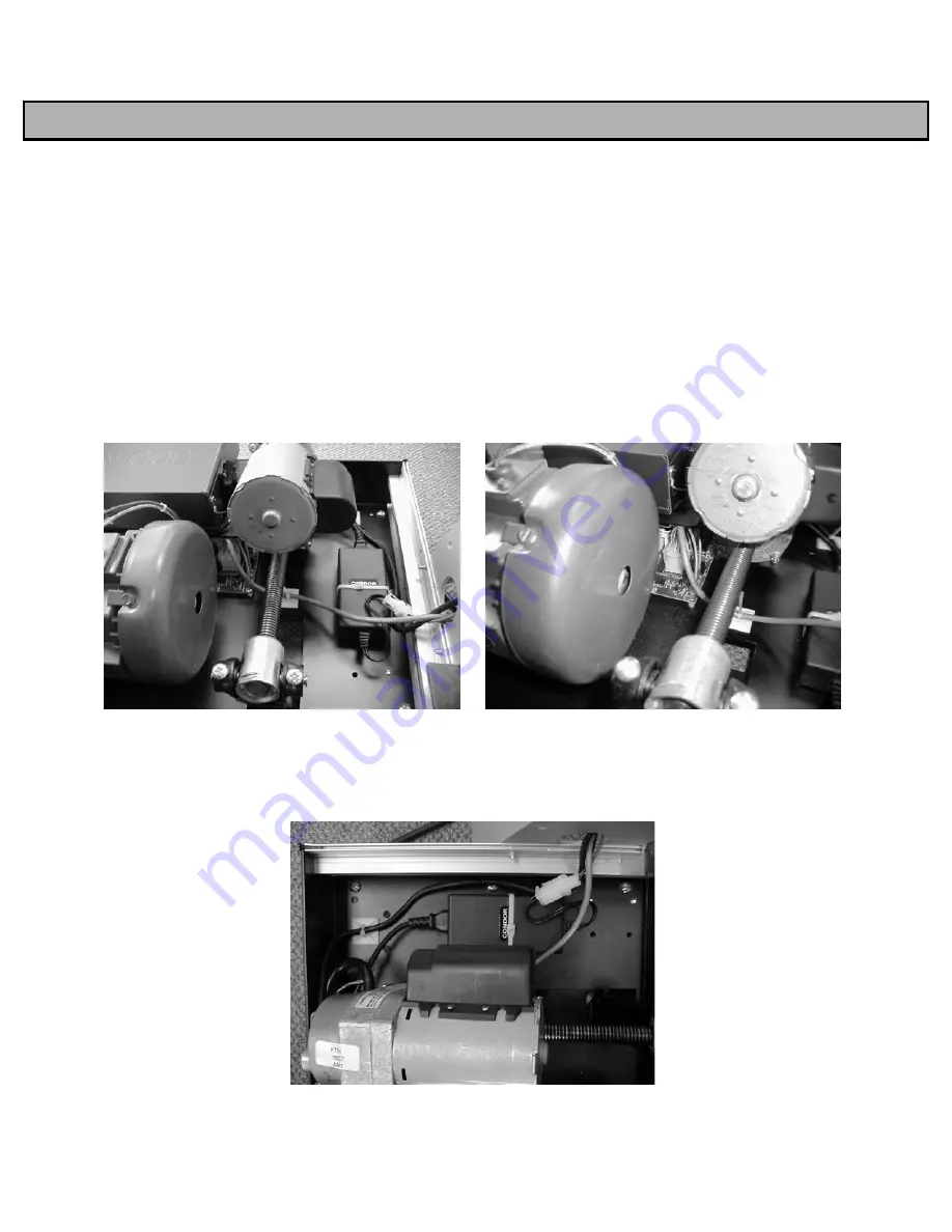
On the Road Runner, there are three wire harnesses that must be connected after the
upright assembly is mounted to the frame of the treadmill.
1.
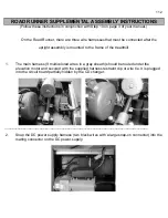
The main harness (9 multicolored wires in a gray sheath) should be routed under the
elevation motor and secured with the supplied harness restraint clip or wire tie. It is plugged
into the circuit board partially hidden by the CD changer.
______________________________________________________________________________
2.
Snap the DC power supply harness (two black wires with a large snap-on connector) into the
mating connector on the DC power supply.
Summary of Contents for Cardio Trainer L8
Page 5: ...5 ...
Page 27: ...27 Section 3 Parts Identification L8 L9 BED EXPLODED VIEW 18 ...
Page 28: ...28 L7 BED EXPLODED VIEW L Series Upright ...
Page 29: ...29 L SERIES UPRIGHT EXPLODED VIEW 112 ...
Page 30: ...30 L SERIES MOTOR PAN EXPLODED VIEW 111 ...
Page 35: ...35 COMMERCIAL MOTOR PAN SCR MOTOR CONTROL BOARD ...
Page 36: ...36 L SERIES 110V COMMERCIAL LOWER WIRE SCHEMATIC ...
Page 37: ...37 L SERIES 220V COMMERCIAL LOWER WIRE SCHEMATIC ...
Page 40: ...40 L SERIES SCR UPPER WIRE HARNESS WIRING DIAGRAM ...
Page 42: ...42 L SERIES HOME MOTOR PAN WIRING SCHEMATIC ...
Page 47: ...47 L SERIES HOME MOTOR PAN WIRING SCHEMATIC PWM MOTOR CONTROL BOARD W RELAY ASSEMBLY ...
Page 48: ...48 PWM MOTOR CONTROL BOARD W RELAY ASSEMBLY ...
Page 49: ...49 L SERIES PWM UPPER WIRE HARNESS WIRING DIAGRAM ...
Page 50: ...50 EXECUTIVE TRAINER LCD WIRING SCHEMATIC ...
Page 110: ...110 L SERIES ROAD RUNNER LOWER WIRING DIAGRAM ...
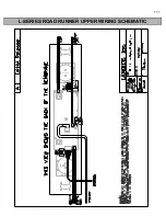
Page 111: ...111 L SERIES ROAD RUNNER UPPER WIRING SCHEMATIC ...


