background image

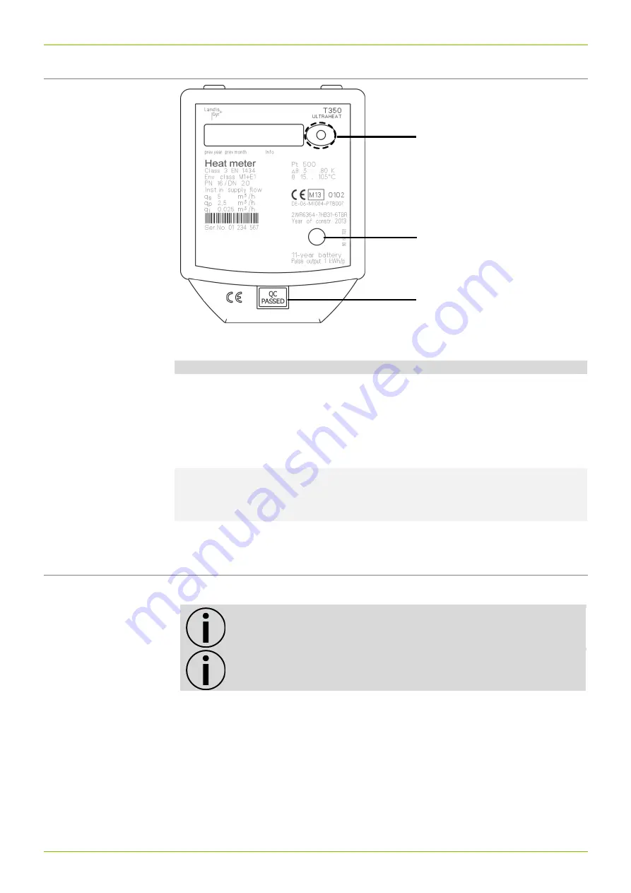
Operating elements 


13/21 


Operating elements 


Fig. 12: Operating elements 

No.  Name 

Description 

Note 

Button 

Switches  to  the  next 
loop  and  display  value 
within a loop.  

To  switch  between  the 
displayed  values:  press 
the button shortly (approx. 
3 s); 
To  switch  between  the 
loops:  press  the  button 
longer (approx. 10 s) 

Optical interface 

Allows  data  communi-
cation with a computer 
with 

the 

necessary 

service software. 


Calibration  rele-
vant security seal 


6.1  Displaying current meter status 

The meter displays the current meter status in kWh, MWh, MJ or GJ. 


Note:

 In order to prevent reading errors, the decimal places of the 

values displayed are marked with a frame. 


Note:

 Both display range and data displayed can differ from the 

description depending on the appliance parameterization. Certain 
button functions can also be blocked. 


Summary of Contents for ULTRACOLD 2WR6 Series

Page 1: ...ULTRAHEAT T350 2WR6 ULTRACOLD T350 2WR6 Technical Description 32 14 101 001 b Date 19 03 2018 Landis Gyr GmbH Ultrasonic heat and cooling meter T350 2WR6 Residential and district heating...

Page 2: ...verall length 110 mm 130 mm 190 mm Suitable for small mounting locations due to compact construction Construction for residential heating for 105 C and for district heating for 130 C 15 monthly values...

Page 3: ...________________________________________ 13 User loop_______________________________________________________________14 Service loop_____________________________________________________________14 6 2 P...

Page 4: ...two temperature sensors and an electronic unit that calculates the energy consumption from the volume and temperature difference The meter combines modern microcomputer technology with innovative ultr...

Page 5: ...and cooling systems may install and remove the meter Only install or remove the meter when the pipes are de pressurized After installing the meter check the leak tightness of the system Warranty and...

Page 6: ...please observe legal regulations in particular those governing the labelling and packaging of hazardous goods Do not open the batteries Do not bring batteries into con tact with water or expose to te...

Page 7: ...als may be different LCD 7 digit Optical interface Standard EN 1434 3 Communication Optional M Bus or pulse output Protocol IEC 870 300 baud in Nb Separability Always detachable cable length 1 m Tempe...

Page 8: ...0 5 1 5 1 5 110 G 3 4 3 15 6 150 3 9 1 2 1 1 5 130 G1 3 15 6 160 3 8 1 2 1 5 1 5 190 G1 3 15 6 160 3 8 1 2 1 5 2 5 130 G1 5 25 10 200 5 6 1 8 1 5 2 5 190 G1 5 25 10 200 5 6 1 8 1 5 Tolerance of press...

Page 9: ...on situations and the following examples of installation Fit the temperature sensors in the same circuit as the meter Seal the temperature sensor and the fittings to protect against manipula tion If y...

Page 10: ...tes for sensor adapter set A mounting set is included for meters with 5 2 45 mm temperature sen sors With this you can fit the temperature sensor directly immersed into an in sert or a ball valve for...

Page 11: ...rob lems with condensation Fit the immersion sleeves so that the temperature sensor is positioned vertically downwards or horizontally Note Always install the volume measurement unit on the hot side F...

Page 12: ...Dimension of electronic unit 12 21 5 Dimension of electronic unit Fig 10 Dimensions of electronic unit Fig 11 Wall adapter view from above and side...

Page 13: ...ical interface Allows data communi cation with a computer with the necessary service software 3 Calibration rele vant security seal 6 1 Displaying current meter status The meter displays the current m...

Page 14: ...r 0034321 kWh Energy previous year on set day Previous year 00923 12 m Volumes previous year on set day Previous year 12 Fh Missing hours previous year Previous year C Code input for parameterization...

Page 15: ...eter can be supplied with power by a battery or by a power supply mod ules as preferred Options 6 years battery 11 years battery Power supply 24 V AC DC 24 V safety extra low voltage Voltage 12 36 V A...

Page 16: ...e 1 5 m pre assembled PVC LIYY 2 x 0 25 mm2 tin coated ex ternal diameter 3 6 mm Note When reading via M Bus the permissible average reading frequency must not be exceeded 1 every 3 h at 2400 baud 1 e...

Page 17: ...elivery condition F1 Interruption in the hot side temperature sensor Exchange the meter F2 Interruption in the cold side temperature sensor Exchange the meter F3 Electronics for temperature evaluation...

Page 18: ...als K Communication Code Without communication interface 0 With pulse output 1 With M Bus 5 Manufacturer s label Code Logo Landis Gyr 00 Other labels on request xx County where used Code Dial plate fo...

Page 19: ...East English P4C 14 digit is Z Dial plate for Australia English P5C 14 digit is Z Dial plate for Moldavia Romanian P6C 14 digit is Z Dial plate for Spain Spanish P7C 14 digit is Z Dial plate for Serbi...

Page 20: ...1 5 110 G 3 4 150 3 9 C 2 5 190 G1 210 5 3 D 2 5 130 G1 200 5 6 E The indicated pressure loss of a flow sensor is at nominal flowrate qp With the Kv Factor which defines the flow rate at a pressure l...

Page 21: ...21 21 Landis Gyr GmbH Humboldtstrasse 64 90459 Nuremberg Germany...

Reviews: