4-7
ALIGN MENT
4-7.1
Wheel Align ment
DAN GER
TO PRE
VENT A LIFE THREAT
EN
ING
AC CI DENT:
1. SUP
PORT TRAILER AND UN
DER
-
CAR
RIAGE SO TIRES ARE OFF THE
GROUND.
2. SUP
PORT THE TRAILER AND UN
-
DER
CAR
RIAGE ON JACK STANDS
WITH SUF FI CIENT CA PAC ITY TO SUP -
PORT THE TO
TAL WEIGHT OF THE
TRAILER AND ANY LOAD WHICH IT
MAY BE CAR RY ING.
When trailer tires show signs of scuff
ing,
feather- edging or un even wear, ex am ine the trailer
for dam
aged sus
pen
sion (frame, shocks, link
age,
etc.), axle, wheel bear
ings and wheels. Proper
wheel align
ment and wheel bear
ing ad
just
ment is
es sen tial for proper tire wear. The sim plest form of
check
ing wheel align
ment “toe” is by run
ning the
trailer over a “SCUFF GAUGE”. A scuff gauge
read
ing of 16 feet or less per mile is con
sid
ered
sat
is
fac
tory. If a scuff gauge is not read
ily avail
-
able, or edge wear on one side of a tire is oc cur -
ring sig ni fy ing posi tive or nega tive cam ber, align -
ment can be checked as fol lows:
a.
Re
move wheel, hub and bear
ing as
sem
-
blies.
b.
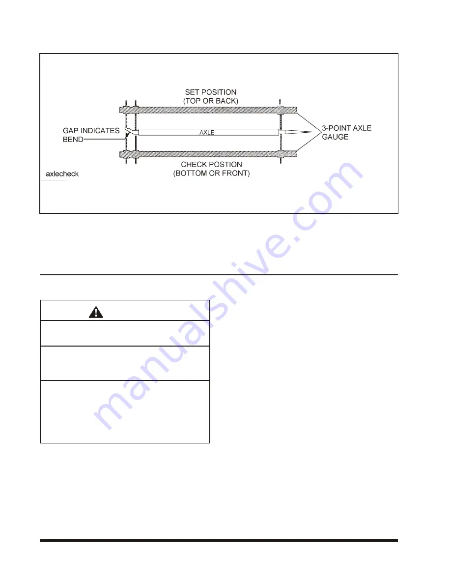
Place a 3- point axle gauge against the front
side of the axle, and ad just each axle gauge
point to the axle. (Dou
ble point end against
the in ner and outer wheel bear ing sur faces of
the spin dle be ing checked and the other point
on the in
ner bear
ing sur
face on the other
spin dle.)
(See Fig ure 4-5).
c.
Move the axle gauge and place against the
back side of the axle. If ei ther of the points of
dou ble point end fails to touch the axle sur -
face, a bent spin dle is evi dent. A point gap of
.015" or more is con
sid
ered ex
ces
sive tire
“toe” and the axle must be re placed
(See Fig -
ure 4-5)
.
4-12
FIG URE 4-5 CHECK ING AXLE FOR BEND
Summary of Contents for 318C
Page 3: ...MODELS 318C BOEING TRAILER OPERATOR S MANUAL PURCHASED FROM DATE ADDRESS PHONE NO SERIAL NO i...
Page 8: ......
Page 12: ......
Page 32: ...3 20 FIGURE 3 6 STEPS FOR LOADING AND UNLOADING...
Page 36: ...3 24 FIGURE 3 8 REAR IMPACT GUARD AND ANTILOCK BRAKE SYSTEM...
Page 52: ...4 14 FIGURE 4 6 CHECKING AXLE ALIGNMENT FIGURE 4 7 EXAMPLES OF CAMBER...
Page 56: ...4 18 FIGURE 4 10 AXLE AND BRAKE ASSEMBLY...
Page 64: ...4 26 FIGURE 4 16 MOUNTING TIRES AND WHEELS FIGURE 4 17 STUD TIGHTENING SEQUENCE...
Page 76: ...5 10 NOTES...


