4-6.3
Gooseneck Lock Rebuilding Procedure:
Refer to
Figure 4-8
for parts identification and
proper parts orientation.
a.
Disassemble the lock and inspect the top
plate for cracks or elongated holes. Cracked
top plates must be discarded, but a top plate
with elongated holes may be rebuilt after
building the holes up and reboring them.
b.
Lubricate the lock pin holes with Neverseez
or its equivalent.
c.
Insert the lock jaws into the top plate with
the 2-7/8" bore toward the face of the top
plate.
d.
Drive the lock pins through the top plate and
the lock jaw pin holes until the lock pins are
flush with the face of the top plate.
e.
Secure the lock pins with cotter pins.
f.
Check to be sure the lock jaws can move
freely and install a 2" diameter plug in the lock
jaws.
g.
The yoke must fit precisely for maximum
service life and proper lock function. Bend the
tips of the yoke slightly outward.
h.
Slide the yoke into the top plate with the
threaded hole in the yoke facing upward and
tap it into position.
i.
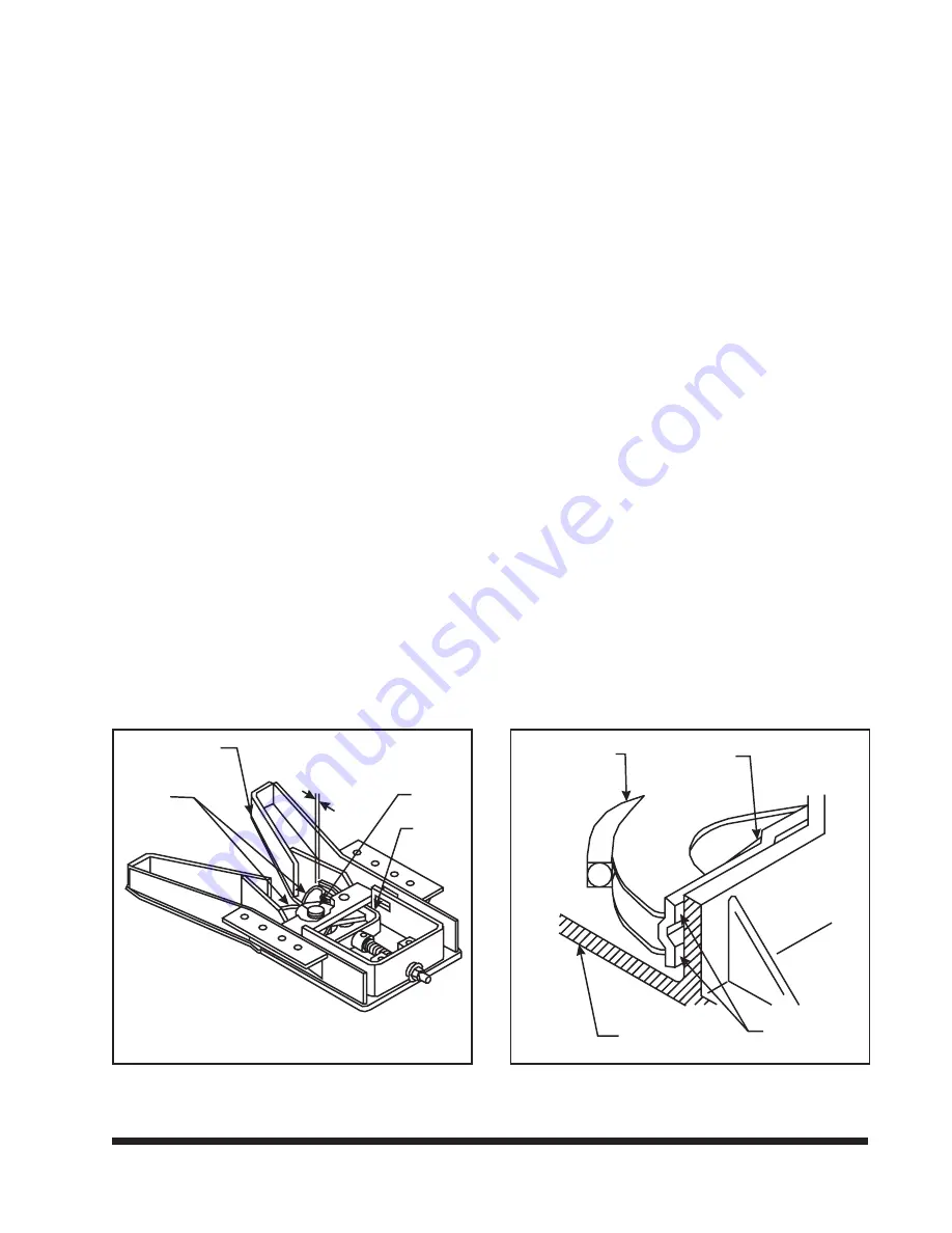
Check the position of the yoke tips. They
must be flush with the ends of the locks or
must not extend more than 1/32" beyond the
ends of the locks
(See Figure 4-6).
If the
yoke are short of the ends of the locks, it will
be necessary to grind the outside surfaces of
the yoke with a belt sander or grinder until it
fits precisely into place
(See Figure 4-6).
If
the yoke extends beyond the ends of the
locks, it will be necessary to build up the con-
tact surface of the yoke with weld using a low
hydrogen E70XX welding rod and grind the
surfaces back down to the proper fit
(See Fig-
ures 4-6 and 4-7).
IMPORTANT
NEVER GRIND OR WELD ON THE INSIDE SUR-
FACE OF THE YOKE OR ON THE LOCKS.
j.
There are two contact surfaces
(See Figure
4-7)
on the outside of each yoke tip. All four
surfaces must have full area contact with the
top plate ribs. Continue the weld, grind, and fit
process until the yoke has full contact and the
yoke tips are flush with the ends of the locks.
k.
Lube both the inside and outside friction
surfaces of the yoke and then slide it into the
top plate with the threaded hole facing up.
l.
Install the spring between the yoke and the
top plate. Insert the yoke shank through the
top plate, spring, and into the yoke. Make
sure that the predrilled recess in the yoke
shank aligns with the threaded hole in the
yoke.
4-11
TOP PLATE
LOCK
JAW
PLUG
YOKE
checking yoke position
0”
1/32
+
-
Figure 4-6 Checking Yoke Position
LOCK JAW
YOKE
TOP PLATE
CONTACT
SURFACE
yoke contact surfaces
Figure 4-7 Yoke Contact Surfaces
Summary of Contents for 325C
Page 2: ......
Page 8: ......
Page 12: ......
Page 36: ......
Page 44: ...4 8 Figure 4 3 Models 325 326 327 329C Wiring Diagram...
Page 54: ...4 18 Figure 4 13 Checking Axle Alignment Figure 4 14 Examples of Camber...
Page 59: ...4 23 Figure 4 17 Axle and Brake Assembly...
Page 68: ......
Page 78: ...NOTES 5 10...
Page 79: ......

