4-7.2
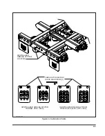
See
Figure 4-10
for Tandem/Triple Axle
Air Ride Suspension drawings.
a.
Physically check all nuts, bolts, and air line
fittings for proper torque (see torque chart be-
low).
AIR SUSPENSION TORQUE CHART
Size
1-1/8"-7
1/2"-13
*3/4"-16
3/4"-10
Torque in
Ft. Lbs.
**800
or
550
35
35
150
* Air Spring Connections Only.
** First number listed is torque required if bolt
head designated with Neway; Second number
listed is torque required if bolt head designated
with Holland Neway.
b.
Check all other suspension components for
any sign of damage, looseness, wear or
cracks.
c.
With trailer on level surface and air pressure
in excess of 65 psi, all air springs should be
of equal firmness. The height control valve on
right side of front axle controls all air springs
on tandem axle suspensions.
d.
The height control valve on right side of
center axle controls ride height for all air
springs on triple axle suspension.
4-15
Figure 4-10 Tandem/Triple Axle Air Ride Suspension System
Summary of Contents for 325C
Page 2: ......
Page 8: ......
Page 12: ......
Page 36: ......
Page 44: ...4 8 Figure 4 3 Models 325 326 327 329C Wiring Diagram...
Page 54: ...4 18 Figure 4 13 Checking Axle Alignment Figure 4 14 Examples of Camber...
Page 59: ...4 23 Figure 4 17 Axle and Brake Assembly...
Page 68: ......
Page 78: ...NOTES 5 10...
Page 79: ......


