5
TROUBLESHOOTING
Troubleshooting should be performed by a trained and competent technician. Landoll Corporation is not
responsible for equipment that is improperly maintained. Contact an authorized Landoll Service center or
the Landoll factory for servicing.
5-1
ELECTRICAL
Most electrical system problems show up as a burned out light or fuse, or inoperative electrical compo-
nent. Wiring, grounds, or components may be at fault. Locate the symptom in this section that best identi-
fies your electrical problem. Check out each possible problem under that symptom. If the problem cannot be
located, see an automotive electrical specialist.
SYMPTOM
PROBLEM: REMEDY
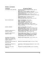
NO LIGHTS
Fuse blown:
replace fuse.
Connection at plug-in:
tighten connection.
Broken or corroded wires:
replace wire.
Ground wire loose:
clean and tighten ground.
LIGHTS FLICKERING
Wires shorted or loose:
locate, insulate, replace, or tighten.
Grounding through fifth wheel:
locate broken ground wire (tractor
or semitrailer).
LIGHTS DIM
Voltage difference between semitrailer & tractor:
match bulbs
with tractor voltage.
Grounding through fifth wheel:
locate broken ground wire (tractor
or semitrailer).
LIGHTS BRIGHT & BURN OUT
Voltage difference between semitrailer & tractor:
match bulbs
with tractor voltage.
FUSE BLOW-OUT OR CIRCUIT
BREAKER TRIPPING
Vibration:
locate source of vibration and repair.
Short circuit:
replace fuse and try all accessories. If fuse blows
right away, locate short and repair.
LAMP BULB BURN OUT
Vibration:
locate source of vibration and repair.
Short circuit:
replace fuse and try all accessories. If fuse blows
right away, locate short and repair.
Loose connection:
check lamp sockets and ground connections.
Intermittent short:
locate short and repair.
Improper voltage:
check voltage regulator output.
5-1
Summary of Contents for 325C
Page 2: ......
Page 8: ......
Page 12: ......
Page 36: ......
Page 44: ...4 8 Figure 4 3 Models 325 326 327 329C Wiring Diagram...
Page 54: ...4 18 Figure 4 13 Checking Axle Alignment Figure 4 14 Examples of Camber...
Page 59: ...4 23 Figure 4 17 Axle and Brake Assembly...
Page 68: ......
Page 78: ...NOTES 5 10...
Page 79: ......


