background image

2.

Align the front axle using the method

outlined in

Section 4-8.2a.

3.

After proper alignment has been obtained,

tighten the suspension pivot bolt nut to the

torque listed in the table in

Section 4-7.1

.

4.

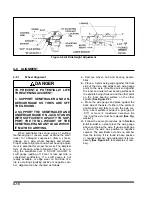
Align the rear axle to the front axle. Locate

the rear axle equalizer beam pivot bolt in

hanger at front end of driver’s side rear axle

equalizer beam. Loosen the suspension

pivot bolt lock nut. Rotate the head of the

pivot bolt. For axle alignment forward, rotate

bolt head clockwise. For axle alignment

rearward, rotate the bolt head

counter-clockwise. The rear axle should be

parallel with the front axle, with the

dimensions Y and Y1 being the same.

5.

Tighten the suspension pivot bolt nut to the

torque listed in the table in

Section 4-7.1

.

4-9 BRAKE SYSTEM MAINTENANCE

CAUTION

USE GREAT CARE IF WHEELS OR

BRAKE DRUMS MUST BE HANDLED.

THEY MAY BE VERY HOT AND CAN

CAUSE INJURY.

4-9.1

General

.

a.

Check air hoses for chafing, bends, kinks,

or damaged fittings. Replace defective hoses.

b.

Check the brake system for loose, missing,

deformed, or corroded fasteners. Replace

and tighten defective hardware.

c.

Check brake linings for excessive wear or

distortion.

d.

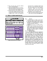
Drain air reservoir daily. A drain cock on the

bottom of each air reservoir vents the tank to

drain collected water and oil. If held open, air

pressure in the tanks is relieved, causing the

emergency or parking brakes to be applied

(See Figure 4-10).

4-9.2

Spring Air Brake

Check for faulty units. Check the condensation

holes on the underside of the brake chambers to

make sure they are open. The spring brake has

two brake chambers, a service chamber and and

an emergency chamber or spring chamber

(See

Figure 4-10).

Service brake chambers should be

disassembled and cleaned at 50,000 miles or

yearly. The diaphragm and any marginal parts

should be replaced. When replacing the service

diaphragm, replace the corresponding parts for the

other chamber on the same axle (to aid in even

brake application and release). Examine yoke pin

for wear and replace as necessary. The spring

chamber should not be serviced. Replace entire

unit (both service and spring chamber) if spring

chamber becomes faulty.

4-13

Figure 4-10 Drain Cock Locations

Summary of Contents for 336C

Page 1: ...MODEL 336C CAR CARRIER OPERATOR S MANUAL 1900 NORTH STREET MARYSVILLE KANSAS 66508 785 562 5381 F 276 1299 12 99...

Page 2: ...defective part This warranty is void if any part not supplied by LANDOLL is used in assem bly or repair or if the machine has been altered abused or neglected LAN DOLL repair parts are warranted for n...

Page 3: ...MODEL 336C CAR CARRIER OPERATOR S MANUAL PURCHASED FROM DATE ADDRESS PHONE NO SERIAL NO...

Page 4: ...volved in individual prob lems between you your dealer or Landoll Manufacturing To contact NHTSA you may either call the Auto Safety Hotline toll free at 1 800 424 9393 or 366 0123 in Washington D C a...

Page 5: ...THE CAB DECK 3 13 3 15 LOADING THE UPPER DECK 3 14 3 16 LOADING THE LOWER DECK 3 15 3 17 SECURING THE LOAD 3 17 3 18 UNLOADING THE LOWER DECK 3 18 3 19 UNLOADING UPPER DECK 3 18 3 20 UNLOADING THE 33...

Page 6: ...IF NOT AVOIDED WILL RESULT IN DEATH OR SERIOUS INJURY WARNING WARNING INDICATES A POTENTIALLY HAZARDOUS SITUA TION WHICH IF NOT AVOIDED COULD RESULT IN DEATH OR SERIOUS INJURY CAUTION CAUTION INDICAT...

Page 7: ...RPORATION 1900 NORTH STREET MARYSVILLE KANSAS 66508 or phone 785 562 5381 or 800 428 5655 or FAX 785 562 3240 SECTION 5 is a troubleshooting guide to aid in diagnosing and solving problems with the se...

Page 8: ......

Page 9: ...H 48 OR 52 OVERALL WIDTH 102 WEIGHT 19 100 19 400 LB UPPER DECK INSIDE WIDTH 87 DECK HEIGHT TRANSPORT POSITION 98 119 LOWER DECK INSIDE WIDTH 94 DECK HEIGHT TRANSPORT POSITION 34 WINCH QUANTITY 6 CAPA...

Page 10: ...150 FT LBS AIR SPRING MOUNTING 1 2 35 FT LBS 3 4 35 FT LBS WHEEL FASTENERS ALL MODELS OUTER SPINDLE NUTS 250 400 FT LBS PILOT WHEEL NUTS 450 500 FT LBS DISK WHEEL INNER WHEEL NUTS 450 500 FT LBS DISK...

Page 11: ...65 81 90 112 9 16 12 55 62 80 100 110 137 9 16 18 60 75 90 112 130 162 5 8 11 75 94 110 137 170 212 5 8 18 85 106 130 162 180 225 3 4 10 130 162 200 250 280 350 3 4 16 150 188 220 275 320 400 7 8 9 12...

Page 12: ...146 75 85 16 115 125 202 218 109 121 20 160 180 248 272 213 237 24 185 215 303 327 238 262 32 250 290 310 340 LANDOLL CORPORATION HYDRAULIC FITTING TORQUE SPECIFICATIONS 37o JIC ORS ORB REV 10 97 THIS...

Page 13: ...stem when air pressure in the emer gency line drops below 70 psi This may be done within the truck using the trailer parking emergency valve or by disconnecting the emergency glad hand 3 1 3 Air Brake...

Page 14: ...the fifth wheel plate of the tractor If necessary connect the tractor hydraulic lines Use the TRAILER TILT CONTROL See Figure 3 2 to raise or lower the king pin plate sufficiently to allow proper cou...

Page 15: ...ify the vehicle coupling is se cure If the tractor disconnects from the semitrailer locate the source of the coupling failure repair before continuing and repeat Steps 3 3 3 and 3 3 4 3 3 5 Check that...

Page 16: ...ylinders 3 5 3 Verify that the traveling undercarriage is completely slid back to transport position Shut off hydraulic power 3 5 4 Check the operation of all lights and sig nals on the semitrailer fo...

Page 17: ...icle speed exceeds 4 mph the light should remain off unless a fault occurs or the keyswitch is turned off then on again b If the warning lamp does not go off a fault exists in the trailer ABS If fault...

Page 18: ...equalized or not tail heavy 3 8 3 If the trailer is partially loaded move the undercarriage forward but not enough to cause the trailer to be tail heavy Do not move the undercarriage after the trailer...

Page 19: ...arms are ex tended raising that part of the upper deck CENTER This is the neutral position DOWN In this position the arms are re tracted lowering that part of the up per deck 3 9 5 The UNDERCARRIAGE T...

Page 20: ...ition the clutch is disen gaged and the winch will free wheel To lock in the disengaged position pull handle all the way out and turn a quarter turn 3 10 2 The WINCH HYDRAULIC CONTROLS See Figure 3 2...

Page 21: ...e POWER SWITCH must be turned off and back on again 3 11 3 The DECK SELECTOR is in the middle of the front panel LOWER When the deck selector is in this po sition the functions listed BELOW this switc...

Page 22: ...CONTROL until the arm is locked in position 3 12 4 Verify that the arm is locked by looking through the window to see if the cogs are engaged See Figure 3 5 WARNING DO NOT PUT FINGERS OR OBJECTS INTO...

Page 23: ...overload any component of the trailer or cause an unsafe condition 3 13 2 Park the tractor trailer in a straight line on a level even surface Set the tractor brakes and release the semitrailer brakes...

Page 24: ...3 12 Figure 3 7 Lining Up the Over the Cab Deck Figure 3 8 Loading the Over the Cab Deck...

Page 25: ...nch 2 See Fig ure 3 6 to the first vehicle and pull it to the front of the upper deck Secure the vehicle so it will not roll forward or backward 3 14 9 Tilt the front of the trailer back down as far a...

Page 26: ...15 5 Make sure the trailer axles are all the way forward Tilt the trailer with the TRAILER TILT CONTROL until the ap proach plate of the lower deck touches the ground 3 15 6 Connect winch 2 See Figure...

Page 27: ...ise the rear arm to an adequate height to allow clearance for load ing vehicles on the lower deck 3 15 11 Unlock and raise the middle arm to an adequate height to allow clearance for load ing vehicles...

Page 28: ...3 16 Figure 3 11 Loading the Lower Deck...

Page 29: ...e semi trailer is in transport position 3 16 8 Lower the arms front first then middle then rear to allow a minimum clearance of 1 above the vehicles on the lower deck See Figure 3 11 3 17 SECURING THE...

Page 30: ...s the rear of the semitrailer In sure that the load is steering straight so it does not maneuver off the side of the semi trailer WARNING WHEN REMOVING LOAD INSURE THAT THE LOAD IS STEERING STRAIGHT S...

Page 31: ...the tractor 3 21 REAR IMPACT GUARD SYSTEM Vehicle standards FMVSS No 224 Rear Im pact Protection requires all 336 Series trailers manufactured after January 26 1998 to be equipped with a rear impact g...

Page 32: ...3 20 Figure 3 13 Rear Impact Guard and Antilock Brake System...

Page 33: ...rd it s read ing One of the valves is an ABS relay valve with integrated electronic control unit The other valve is an ABS relay valve that is controlled by the elec tronic control unit on the first v...

Page 34: ...n bearings electrical systems and air systems Moisture attracted by warm parts can con dense collect and freeze to immobilize equipment The tractor trailer operator must always be alert for indicators...

Page 35: ...or broken parts must be repaired or replaced at once Determine the cause of any binding or hy draulic leakage at once Correct the problem before using the tractor or semitrailer b Use the Troubleshoo...

Page 36: ...lti purpose Grease Ronex Multi purpose Grease Phil Lube M W Grease MarFax All Purpose 4 ALL YEAR Industrial Oil 32 Estic 32 Condor 32 or Magnus 32 Regal Oil R O 32 5 ALL YEAR Gear Lube SAE 80W 90 Gear...

Page 37: ...ES I I I WINCH GEAR CASE I I 2 c AIR LINE FILTER I R AIR LINE LUBRICATOR I I R 1 c I Inspect R Replace T Tighten Adjust Torque L Lubricate C Clean NOTES a Perform at the time shown Shorten service int...

Page 38: ...s those recommended for auto motive finishes or a non etching non abrasive aluminum cleaner Use a soft cloth or sponge Rinse with clear water and dry with a chamois or cloth to prevent spotting or str...

Page 39: ...E SUSCEPTI BLE TO ACID DETERIORATION a Check the oil level of the tractor wet kit hy draulic tank weekly or after any leakage See Table 4 1 for proper hydraulic oil Check the hydraulic oil level with...

Page 40: ...4 6 Figure 4 3 336C Wiring Diagram...

Page 41: ...ce ment lamps must be equivalent to the factory installed lamp 4 7 336C WIRING PARTS LIST REF DES FUNCTION DS1 FRONT LEFT CLEARANCE LD YELLOW DS2 FRONT RIGHT CLEARANCE LD YELLOW DS3 FRONT LEFT SIDE MA...

Page 42: ...er is transmitting activate the emer gency stop on the transmitter This will dis able the power relay and the transmitter will transmit for 10 seconds The RF and Power Indicator LED s will be on c To...

Page 43: ...Brake Size Ride Height Block Height 12 1 4 Dia 3 5 4 1 4 d Lower the semitrailer by exhausting all air from the system Recheck the ride height e Move the control arms to the down posi tion about 45 fo...

Page 44: ...ying positive or negative cam ber alignment can be checked as follows a Remove wheel hub and bearing assem blies b Place a 3 point axle gauge against the front side of the axle and adjust each axle ga...

Page 45: ...4 11 Figure 4 7 Checking Axle for Bend Figure 4 8 Examples of Camber...

Page 46: ...sure D1 to the other end of the axle in the same manner as in Step 4 Record this measurement See Figure 4 9 6 Set D about 1 8 shorter than D1 to insure proper semitrailer tracking on slope of road 7 A...

Page 47: ...the brake system for loose missing deformed or corroded fasteners Replace and tighten defective hardware c Check brake linings for excessive wear or distortion d Drain air reservoir daily A drain coc...

Page 48: ...ing rod by removing the clevis pin See Figure 4 13 5 Mark all air service lines for proper re installation and disconnect from the brake chamber 6 Remove the brake chamber from the axle brackets d Ins...

Page 49: ...return springs 7 Remove camshaft lock ring spacer washer and camshaft 8 Remove roller pin retainers 9 Remove roller pins and rollers from shoes 10 Remove camshaft bushings and seals from spider 11 Af...

Page 50: ...4 16 Figure 4 12 Axle and Brake Assembly...

Page 51: ...plication 6 Measure the movement of the push rod from the completely released position to the applied position by marking the push rod where it exits the air chamber before and after application 7 If...

Page 52: ...o length 13 If the push rod is not fully engaged in clevis body install a new push rod cut to length 14 Install the slack adjuster on the S cam shaft 15 Rotate the manual adjuster shaft CW until the s...

Page 53: ...le If any portion of the brake sur face exceeds the maximum diameter it must be discarded The maximum is 120 over the nominal new diameter unless stated other wise on the casting The maximum diameter...

Page 54: ...4 20 Figure 4 14 Outboard Mount Hub and Drum Figure 4 15 Inboard Mount Hub and Drum...

Page 55: ...LD CUPS l If studs are marked R or L right hand R hubs should be installed on the curbside of the vehicle left hand L hubs should be in stalled on the driver side DANGER FAILURE TO USE THE CORRECT STU...

Page 56: ...r seating of the bearings and cups in the wheel hub f Loosen the inner adjustment nut so that the wheel will turn freely g Retighten the inner adjustment nut to 50 ft lbs while rotating the wheel to p...

Page 57: ...any foreign objects from between duals 4 12 2 Tire Matching Both tires on the same spindle must be the same size in order to properly distribute the load and braking forces between them The tire must...

Page 58: ...n to 50 foot pounds using the sequence in Figure 4 20 Then tighten to full torque of 450 to 500 foot pounds using the same sequence g Torque will drop after the first 50 to 100 miles of operation Chec...

Page 59: ...4 25 Figure 4 19 Mounting Tires and Wheels Figure 4 20 Stud Tightening Sequence...

Page 60: ...d or cleaned under pressure by first removing the fill plug then removing the bowl e Do not replace the fill plug until the bowl and guard are in position and the clamp ring is locked into place IMPOR...

Page 61: ...irty or clogged Drain oil and replace filter Oil lines dirty or collapsed Clean or replace as necessary Air leaks in pump suction line Repair or replace as necessary Worn or dirty pump Clean repair or...

Page 62: ...educe engine speed Excessive internal leakage Repair or replace part s as needed Restriction in filters or lines Replace filter or flush lines Insufficient heat radiation Clean dirt and mud from reser...

Page 63: ...d wires Replace wire Ground wire loose Clean and tighten ground LIGHTS FLICKERING Wires shorted or loose Locate insulate replace or tighten LIGHTS DIM Voltage difference between trailer tractor Tracto...

Page 64: ...e inflation to correct psi Check axle alignment Overload Do not load above rated tire capacity SHOULDER TREAD WEAR ONE SHOULDER Axle damage Straighten or replace axle Axles not parallel Check axle ali...

Page 65: ...stem improperly connected Re connect gladhands properly Relay Emergency valve plugged Clean valve Defective tractor protection valve Repair or re place Restricted tubing or hose line Locate and elimi...

Page 66: ...ing or lubrication Adjust or lubricate as needed Brake rigging binding Align brakes or replace bent parts Exhaust port of relay valve restricted or plugged Replace valve ALL BRAKES DO NOT RELEASE Air...

Page 67: ...GENCY SYSTEM ONLY APPLIED NO LEAKAGE WITH NORMAL BRAKING Relay emergency valve failure Replace valve EXCESSIVE WATER PRESENT IN BRAKE SYSTEM Reservoir not drained often enough Drain res ervoir daily E...

Page 68: ...rums Pull drums and inspect for any of the following Heat spotted drums grease spot ting blue drums scored drums excessive wear at rivet holes or edges polished drums out of round drums unbalanced dru...

Page 69: ...the solenoids direct and then try the unit Solenoids on spool valve malfunctioning Check solenoids on valve for proper valve switch ing NOTE Since the solenoid valves are hydraulically pilot operated...

Page 70: ...NOTES 5 10...

Reviews: